

Liquid container
a technology for liquid containers and containers, applied in the field of liquid containers, can solve the problems of reduced non-uniform density inclination of pigmented ink in the ink tank, reduced density inclination, and reduced density inclination in the entire ink tank, and achieves the effect of reducing non-uniform density inclination and simplifying structur
- Summary
- Abstract
- Description
- Claims
- Application Information
AI Technical Summary
Benefits of technology
Problems solved by technology
Method used
Image

Examples
first embodiment
[0050] First, an ink-jet recording apparatus including a liquid container according to a first exemplary embodiment of the present invention will be described.
[0051] Ink-jet recording apparatuses are of a non-impact type that can record on various recording media at high speed yet with little noise during recording.
[0052] Ink-jet recording apparatuses are in widespread use as recording mechanisms for printers, word processors, facsimile machines, copying machines, and the like.
[0053] Basically, one such ink-jet recording apparatus includes a body M1000, a feeding section M3022 that feeds recording media such as paper, and an ejecting tray M1004 as shown in FIG. 15.
[0054] As shown in FIG. 16, the ink-jet recording apparatus includes a chassis M3019 and recording mechanisms inside the body thereof. A detachable recording-head cartridge (not shown) for recording on recording sheets that are fed to a recording position is attached to a carriage M4001.
[0055] The recording-head cartr...
second embodiment
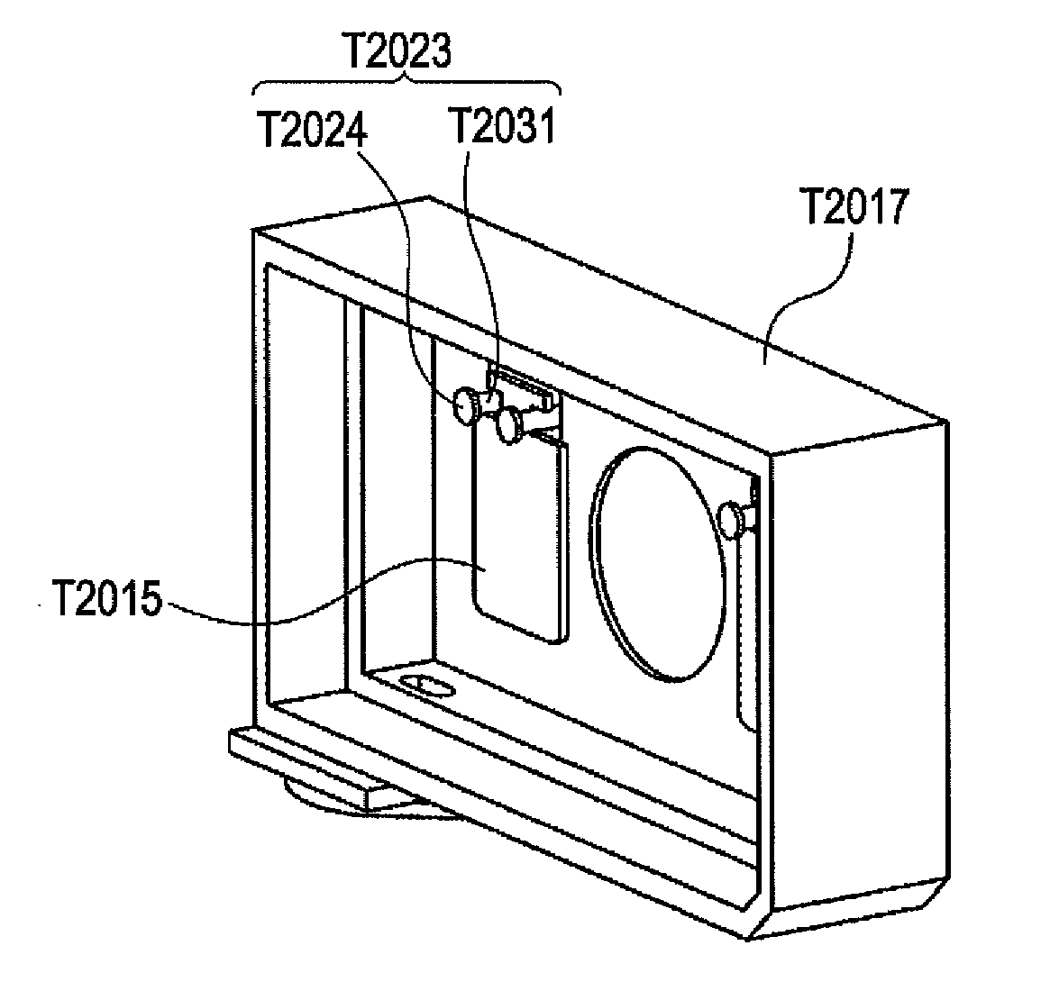
[0104]FIG. 8 is a perspective view illustrating a second exemplary embodiment of the present invention, which is a modification of the liquid container of the present invention, and FIG. 9 is a plan view of an agitating member shown in FIG. 8.
[0105] An ink tank shown in FIG. 8 includes a supporting member T2023 having a tabular shaft and a retaining portion T2024 formed at the end of the shaft. As shown in FIG. 9, an agitating member T2015 has a rectangular hole T2026. According to this structure, a side of the rectangular hole of the agitating member is in contact with a surface (upper surface) of the tabular shaft of the supporting member.
[0106] The agitating member rotates by action of inertial force generated in response to the movement of the carriage. The contact portion between the lip of the hole of the agitating member and the supporting member functions as a rotation axis, and substantially the same agitating effect as in the first exemplary embodiment can be accomplishe...
third embodiment
[0107]FIG. 10 is a perspective view illustrating a third exemplary embodiment of the present invention, and FIG. 11 is a plan view of an agitating member shown in FIG. 10.
[0108] As shown in FIG. 10, an ink tank according to this exemplary embodiment includes supporting members T2023 each having a rail member T2028 with two rails parallel to each other and a retaining portion T2024 formed at the end of the rail member.
[0109] As shown in FIG. 11, the agitating member T2015 includes suspending portions T2029 suspended from the supporting members T2023, slender necks T2030 extending from the suspending portions in the vertical direction, and an agitating portion larger than the necks extending from the necks.
[0110] The rail members T2028 form slits T2032 into which the necks of the agitating member T2015 are fitted, and the agitating member is suspended from the supporting members by the suspending portions. Thus, the supporting members each having the two rail members parallel to th...
PUM
 Abstract
Description
Claims
Application Information