Civil Engineering Machine For Spreading Material For Spreading On Soils Or Base Materials

a technology of civil engineering machine and soil, which is applied in the direction of manure treatment, roads, constructions, etc., can solve the problems of blown binder, dust production, and insufficient anti-dust arrangement of known civil engineering machine to stop dust production to an adequate degr

Active Publication Date: 2010-08-12
WIRTGEN GMBH
View PDF10 Cites 4 Cited by
  • Summary
  • Abstract
  • Description
  • Claims
  • Application Information

AI Technical Summary

Benefits of technology

[0012]The object underlying the invention is to provide a civil engineering machine for spreading material for spreading onto soils or base materials, and in particular a civil engineering machine for spreading binders for stabilising soils or base materials, in which the production of dust when the binder in powder form is being discharged is largely prevented.
[0014]The anti-dust arrangement is characterized in that there is formed below the one or more outlet openings of the spreading arrangement a spreading compartment which is bounded by one or more first anti-dust members, and in that an anti-dust space surrounding the spreading compartment is formed which is bounded by one or more second anti-dust members, at least the second anti-dust members which bound the anti-dust space being of a flexible form such that they are able to sweep along the ground. What is achieved in this way is that dust which occurs when the material for spreading is being discharged is first retained in the spreading compartment which is surrounded by the first anti-dust members, thus enabling the dust to settle on the ground. Quite a high proportion of the dust is trapped by this means at an early stage. The dust which is not retained in the spreading compartment is captured in the anti-dust space which is surrounded by the second anti-dust members. This is an effective way of preventing dust which arises when the material for spreading is being discharged from being able to make its way into the surroundings.
[0017]A preferred embodiment of the invention makes provision for the anti-dust arrangement to have a suction extractor arrangement, which is connected to the anti-dust space, for extracting dust from the anti-dust space. The suction extractor arrangement preferably has a collecting container in which the dust is collected. The dust collected in the collecting container is preferably fed back to the container for material for spreading. The above is a particularly effective way of preventing dust from making its way from the anti-dust space into the surroundings.

Problems solved by technology

When binders in powder form are being spread, the problem arises that dust is produced.
In practice it has been found that the anti-dust arrangement of the known civil engineering machines is not always sufficiently good to stop dust from being produced to an adequate degree.
Particularly in fairly high winds, it may happen that the binder is blown away as it emerges from the outlet of the spreading mechanism, in spite of the anti-dust arrangement.
The problem of dust being produced cannot arise with a stabilizer having an injection arrangement because the material which is milled or tilled up has a liquid binder injected into it in the rotor housing.

Method used


Image

  • Civil Engineering Machine For Spreading Material For Spreading On Soils Or Base Materials
  • Civil Engineering Machine For Spreading Material For Spreading On Soils Or Base Materials
  • Civil Engineering Machine For Spreading Material For Spreading On Soils Or Base Materials

Examples


Embodiment Construction

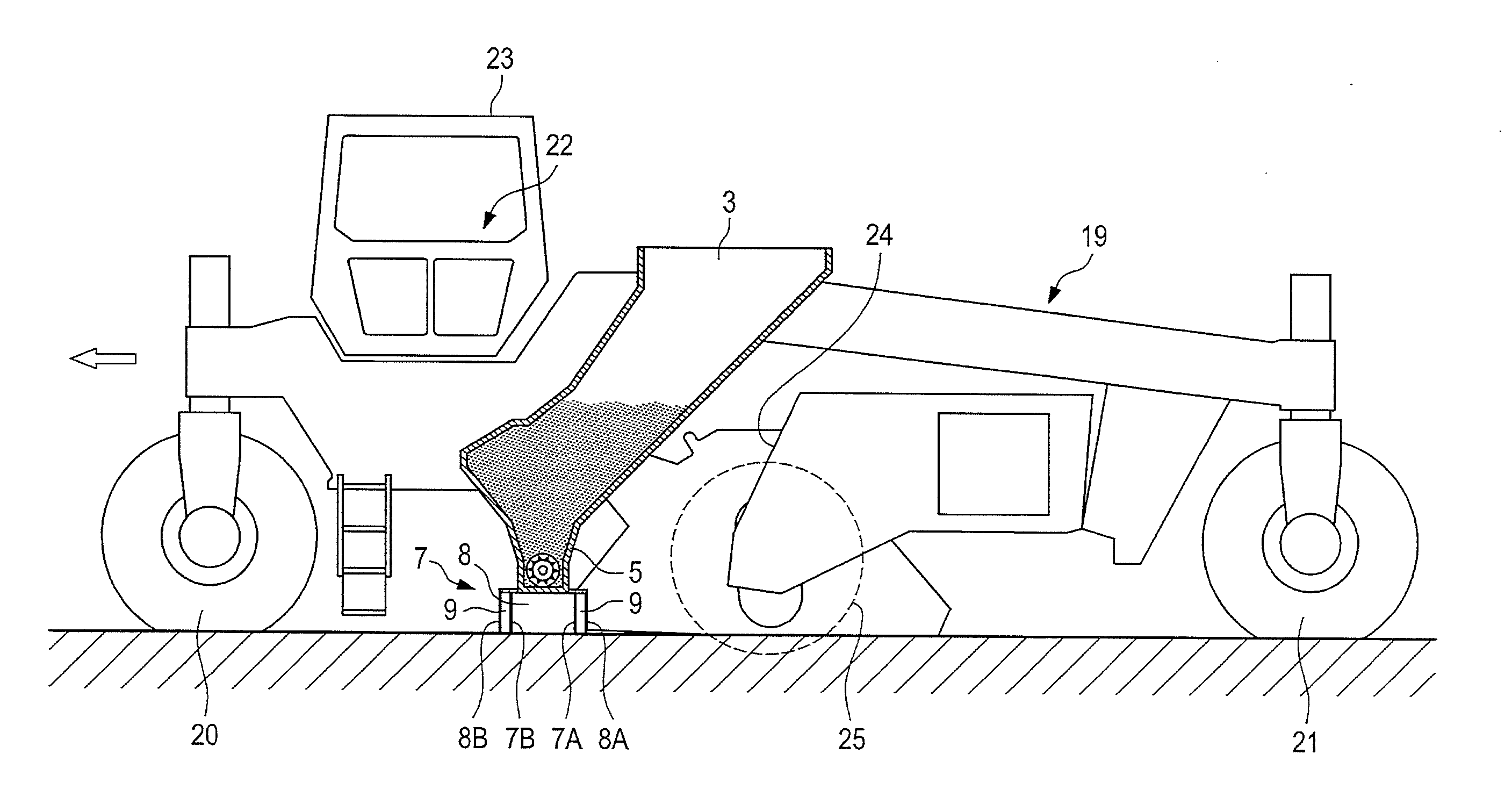
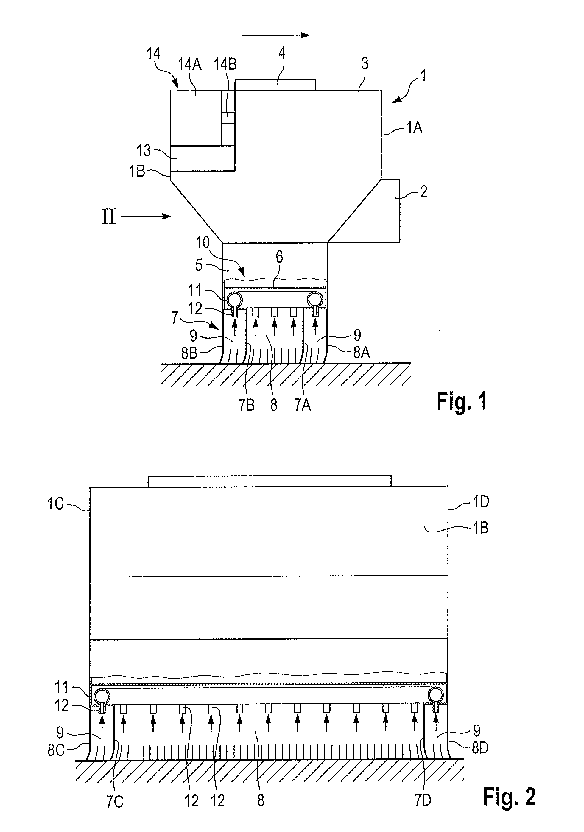
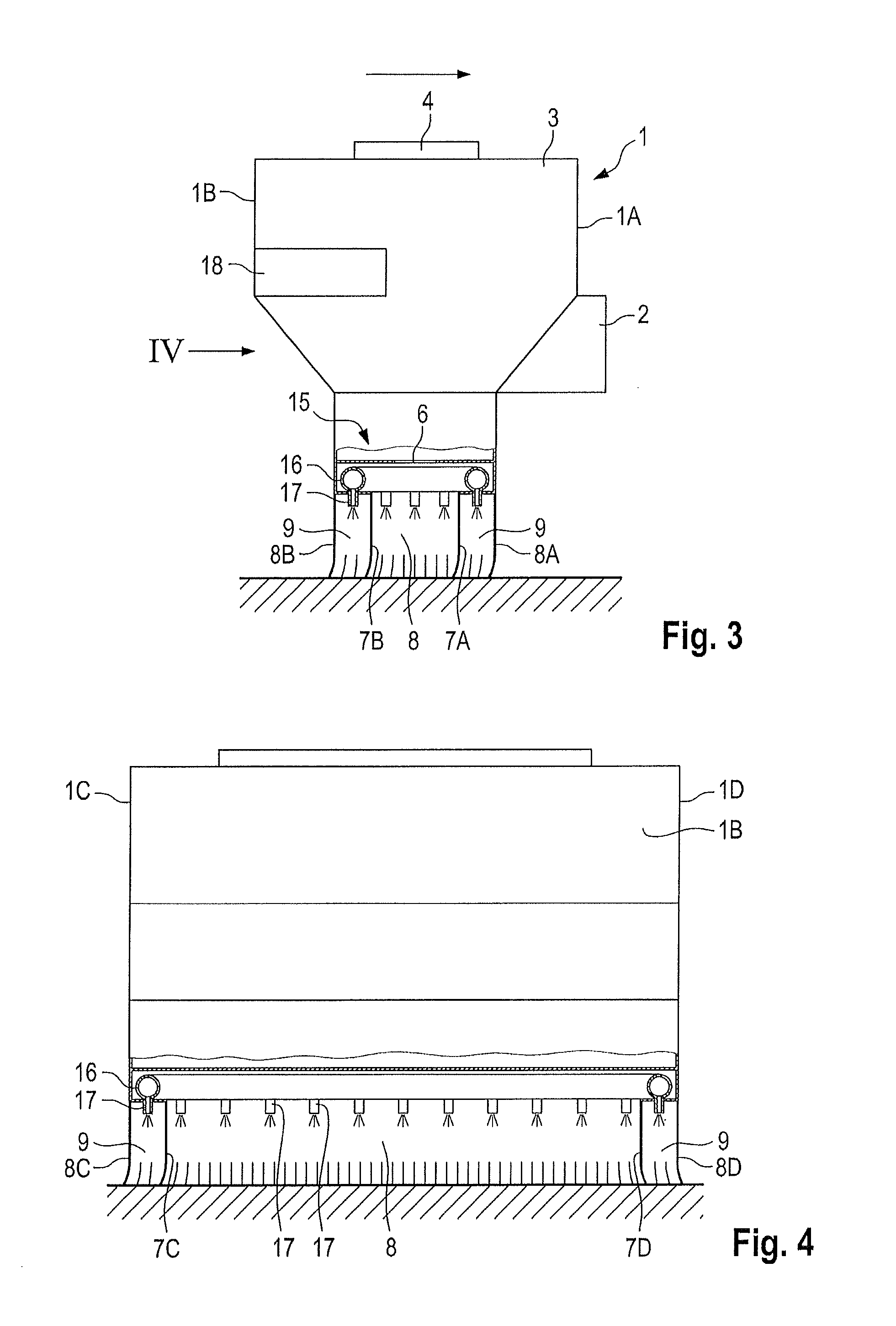
[0031]FIGS. 1 and 2 are highly simplified schematic views showing the main components of a non-self-propelled civil engineering machine for spreading binders for soil or base material stabilization, which will be referred to in what follows as a binder spreader. The binder spreader is mounted on a drawing vehicle (not shown), such as a tractor for example, which tows the binder spreader. The height of the binder spreader relative to the ground can be adjusted on the tractor.

[0032]The binder spreader has a substantially rectangular chassis 1 having a front wall 1A which is at the front in the direction of travel, a rear wall 1B which is at the rear in the direction of travel, and two side walls 1C and 1D. The mounting of the binder spreader on the tractor in such a way as to be adjustable in height is effected by means of a mounting means 2 at the front end of the chassis 1.

[0033]To receive the binder, the binder spreader has an enclosed container 3 for material for spreading which h...


PUM


Abstract

The invention relates to a civil engineering machine for spreading material for spreading on soils or base materials, and in particular to a civil engineering machine for spreading binders for soil or base material stabilization, which has a container (3) for material for spreading to receive the material for spreading and a spreading arrangement (5) having one or more outlet openings for the discharge of the material for spreading. The invention relates in this case both to a civil engineering machine which is intended solely for discharging the binder and to a civil engineering machine, and in particular a stabilizer or recycler, which has a milling or mixing rotor by which, directly after the discharge, the binder can be mixed into the soil or base material which has been milled up. The anti-dust arrangement (7), which is arranged below the outlet openings, is characterized in that there is created below the outlet openings a spreading compartment (8) which is bounded by one or more first anti-dust members (7A, 7B, 7C, 7D) and in that there is created an anti-dust space (9) which is bounded by one or more second anti-dust members (8A, 8B, 8C, 8D). What is achieved in this way is that dust which occurs when the material for spreading is being discharged is first retained in the spreading compartment which is surrounded by the first anti-dust members, thus enabling the dust to settle on the ground. Quite a high proportion of the dust is trapped by this means at an early stage. The dust which is not retained in the spreading compartment is then captured in the anti-dust space which is surrounded by the second anti-dust members.

Description

[0001]Be it known that we, Christoph Menzenbach, a citizen of Germany, residing in Neustadt / Wied, Germany; Heiko Böhme, a citizen of Germany, residing in Vettelschoss, Germany; Cyrus Barimani, a citizen of Germany, residing in Königswinter, Germany; and Günter Hähn, a citizen of Germany, residing in Königswinter, Germany, have invented a new and useful “Civil Engineering Machine For Spreading Material For Spreading On Soils Or Base Materials”. This application claims benefit of German Patent Application DE 10 2009 007 996.3, filed Feb. 7, 2009.BACKGROUND OF THE INVENTION[0002]1. Field of the Invention[0003]The invention relates to a civil engineering machine for spreading material for spreading on soils or base materials and in particular to a civil engineering machine for spreading binders for stabilising the soil or base material. The invention relates in this case both to a civil engineering machine which is intended solely for discharging the binder and to a civil engineering ma...

Claims


Application Information

Patent Timeline
IPC IPC(8): E01C23/00E01C19/12
CPCE01C2301/50E01C21/00E01C19/201E01C19/025
Inventor MENZENBACH, CHRISTOPHBOHME, HEIKOBARIMANI, CYRUSHAHN, GUNTER
Owner WIRTGEN GMBH
Why Eureka
Try Eureka