
Battery pack

a battery pack and battery technology, applied in secondary cell servicing/maintenance, cell structure combination, cell components, etc., can solve the problems of battery cell 111/b> damage, battery cell b>111/b> contact, etc., to reduce the number of components, reduce the change of an outer dimension, and fix the components stably

Active Publication Date: 2010-08-12
MURATA MFG CO LTD
View PDF6 Cites 19 Cited by
  • Summary
  • Abstract
  • Description
  • Claims
  • Application Information

AI Technical Summary

Benefits of technology

The present invention provides a battery pack with a reduced number of components, stable attachment of components, and high positional accuracy. The battery pack includes a battery cell, a circuit board, and a holder that includes a cell holder and a circuit board holder. The circuit board holder is arranged in a space formed above a terrace portion of the battery cell covered with the cell holder. This structure eliminates the need for an insulating tape to fix the battery cell and ensures stability and accuracy in positioning the components.

Problems solved by technology

However, the battery pack shown in FIG. 14 has had the following problems.
Therefore, there is a fear that, when assembly is performed or a shock is received from the outside, the mounted components come into contact with the battery cell 111 and the battery cell 111 is damaged.

Method used


Image

  • Battery pack
  • Battery pack
  • Battery pack

Examples


first embodiment

1. First Embodiment

[0041](Structure of Battery Pack)

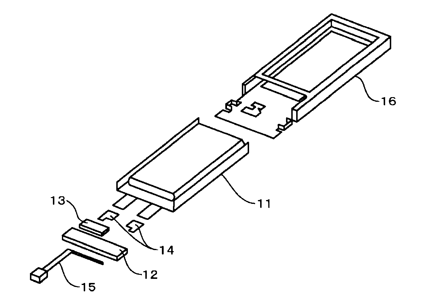
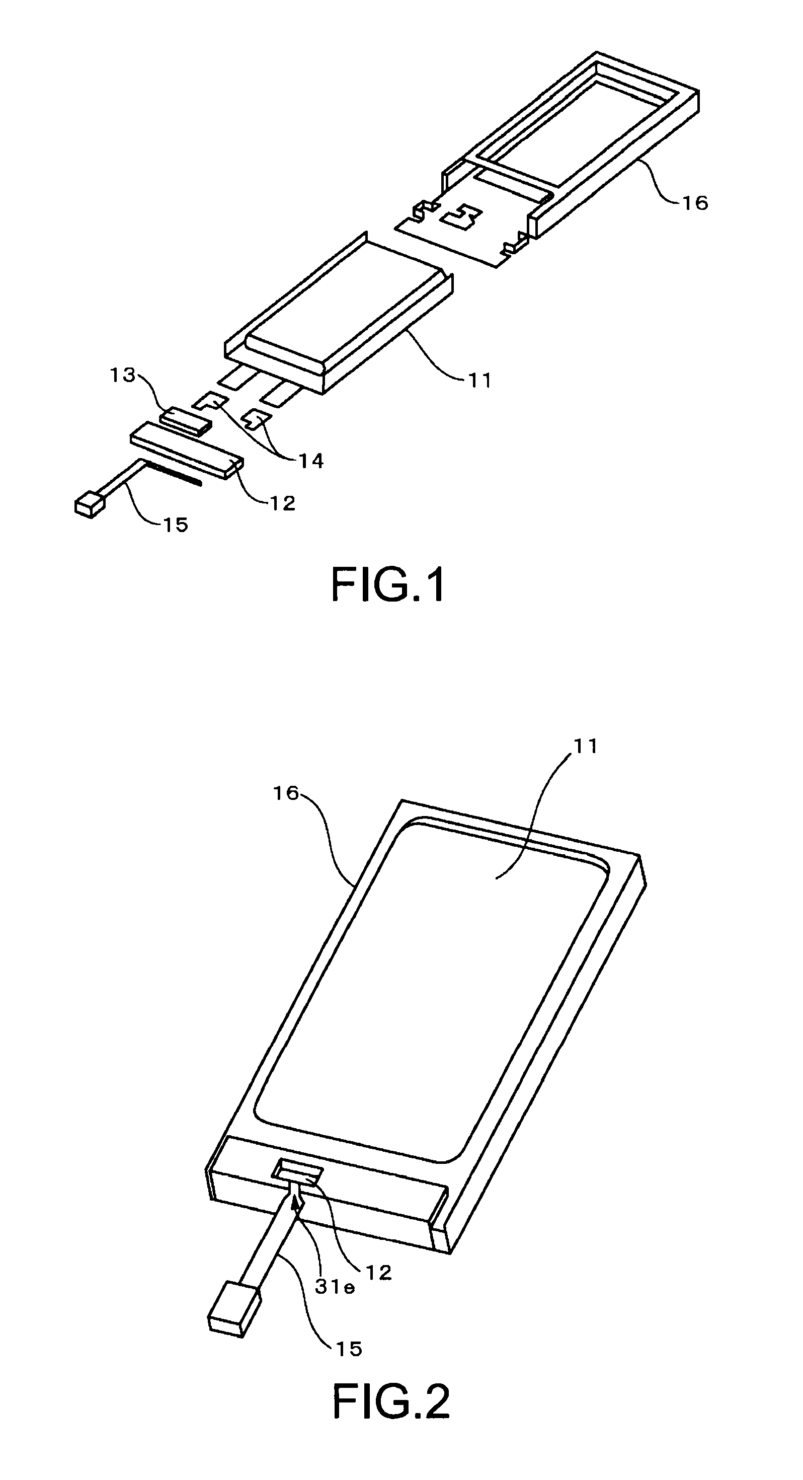
[0042]With reference to FIGS. 1 and 2, a structure of a battery pack according to a first embodiment of the present invention will be described. FIG. 1 is an exploded perspective view showing the structure of the battery pack according to the first embodiment of the present invention. FIG. 2 is a perspective view showing an appearance of the battery pack according to the first embodiment of the present invention.

[0043]As shown in FIG. 1, the battery pack according to the first embodiment of the present invention includes a battery cell 11, a circuit board 12, a safety protection device 13, tabs 14, a lead with connector 15 connected to the circuit board 12, and a holder 16.

[0044]The battery cell 11 and the circuit board 12 are connected to each other via the safety protection device 13 and / or the tabs 14, and the lead with connector 15 is connected to the circuit board 12. A component in which the battery cell 11, the circuit board...

second embodiment

2. Second Embodiment

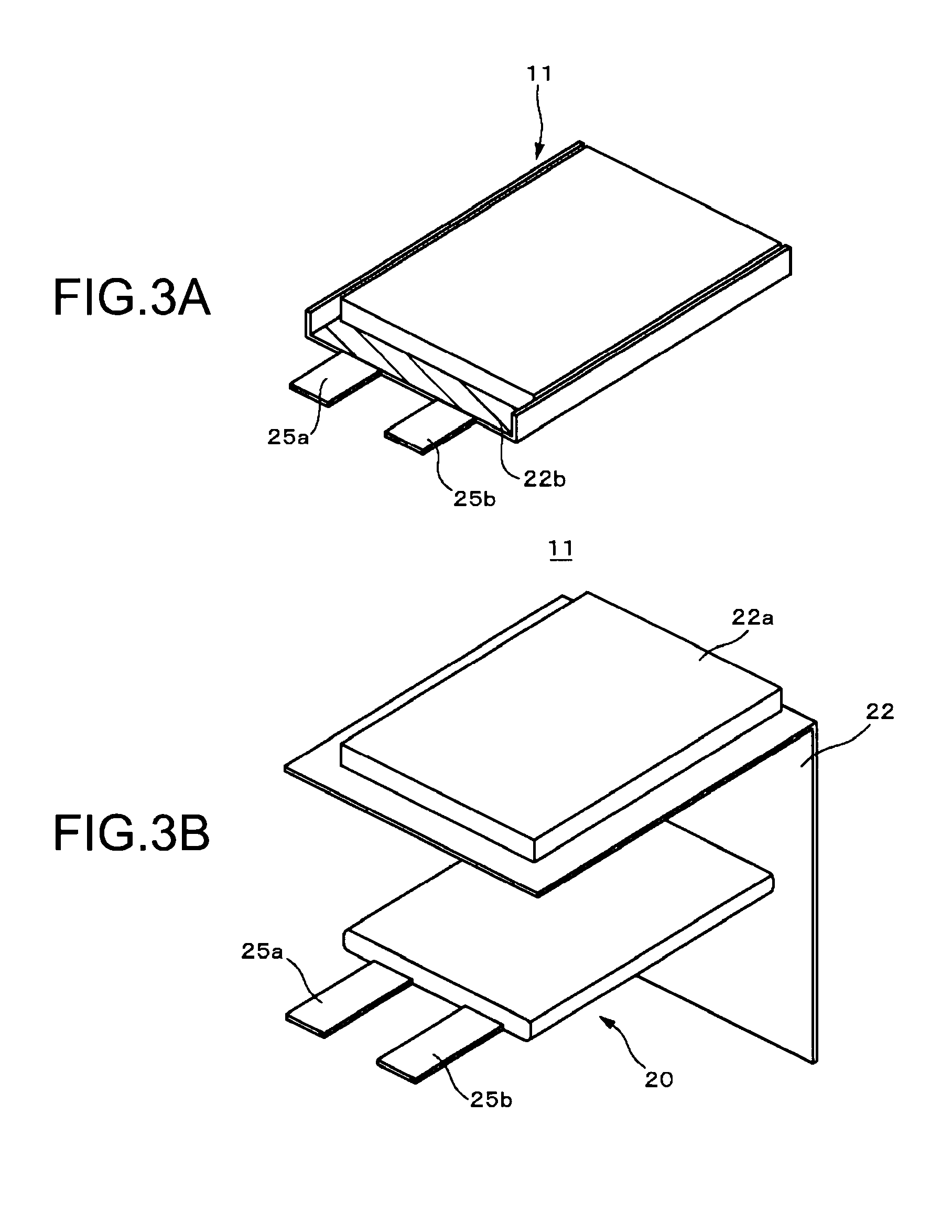
[0143]A battery pack according to a second embodiment of the present invention will be described. The battery pack according to the second embodiment is different from that of the first embodiment in the structure of the battery cell, and other structures of the battery pack are the same as those of the first embodiment.

[0144]Further, a method of producing the battery pack according to the second embodiment of the present invention is also the same as that of the first embodiment of the present invention, except the method of producing the battery cell. Accordingly, a structure of a battery cell and a method of producing a battery cell will be described hereinafter, and detailed descriptions on other structures and the like are omitted because they are the same as those of the battery pack according to the first embodiment.

[0145](Battery Cell)

[0146]A battery cell includes a battery device, a laminate film for covering the battery device, and an electrolytic solut...


PUM

PropertyMeasurementUnit
thicknessaaaaaaaaaa
voltageaaaaaaaaaa
widthaaaaaaaaaa

Abstract

A battery pack includes a battery cell, a circuit board, and a holder. The battery cell includes a battery device covered with a laminate film. The circuit board is connected to the battery cell. The holder includes a cell holder that covers the battery cell and a circuit board holder that covers the circuit board. In battery pack, the circuit board holder covering the circuit board is arranged in a space formed above a terrace portion of the battery cell covered with the cell holder.

Description

BACKGROUND OF THE INVENTION[0001]1. Field of the Invention[0002]The present invention relates to a battery pack. More particularly, the present invention relates to a battery pack incorporated into an electronic apparatus, for example.[0003]2. Description of the Related Art[0004]In recent years, portable electronic apparatuses such as laptop PCs (Personal Computers), cell phones, and PDAs (Personal Digital Asistants) have been prevalent, and as power sources thereof, lithium-ion secondary batteries that have advantages in high voltage, high energy density, and lightweight have been used.[0005]The lithium-ion secondary batteries are widely used as a battery pack that is formed by adding a circuit such as a protection circuit to a battery cell in which a positive electrode, a negative electrode, and a separator and an electrolyte arranged between the positive electrode and the negative electrode are covered with a laminate film.[0006]The battery pack is broadly classified into a so-ca...

Claims


Application Information

Patent Timeline
Patent Type & Authority Applications(United States)
IPC IPC(8): H01M2/10
CPCH01M2/1061H01M10/425H01M10/0525Y02E60/10
Inventor KANO, HIROSHI
Owner MURATA MFG CO LTD
Learn More