Dual clutch transmission

Active Publication Date: 2010-08-19
ZF FRIEDRICHSHAFEN AG
View PDF12 Cites 3 Cited by
  • Summary
  • Abstract
  • Description
  • Claims
  • Application Information

AI Technical Summary

Benefits of technology

[0006]It is the task of the present invention to propose a dual clutch transmission based on the previously described type, in which power shift e

Problems solved by technology

To achieve the desired gear ratio steps in this known double clutch transmission, a vast number of wheel planes are required, and a significant amount of instal

Method used


Image

  • Dual clutch transmission
  • Dual clutch transmission
  • Dual clutch transmission

Examples


first embodiment

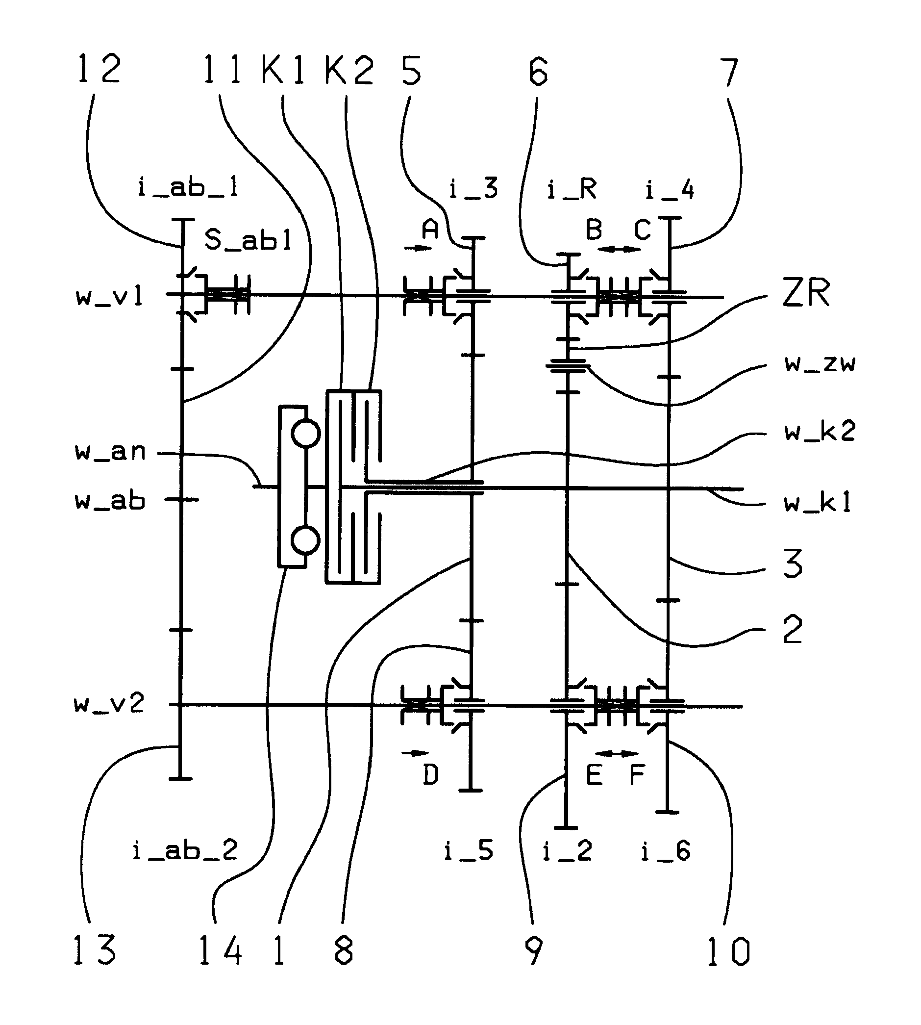
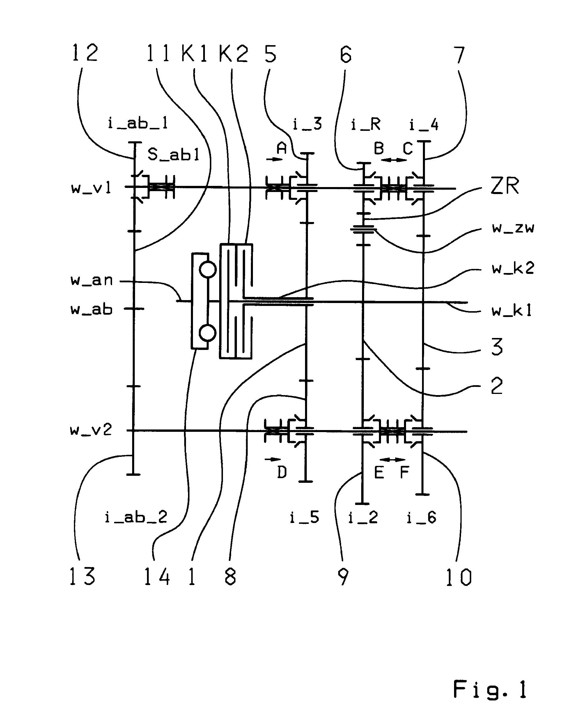
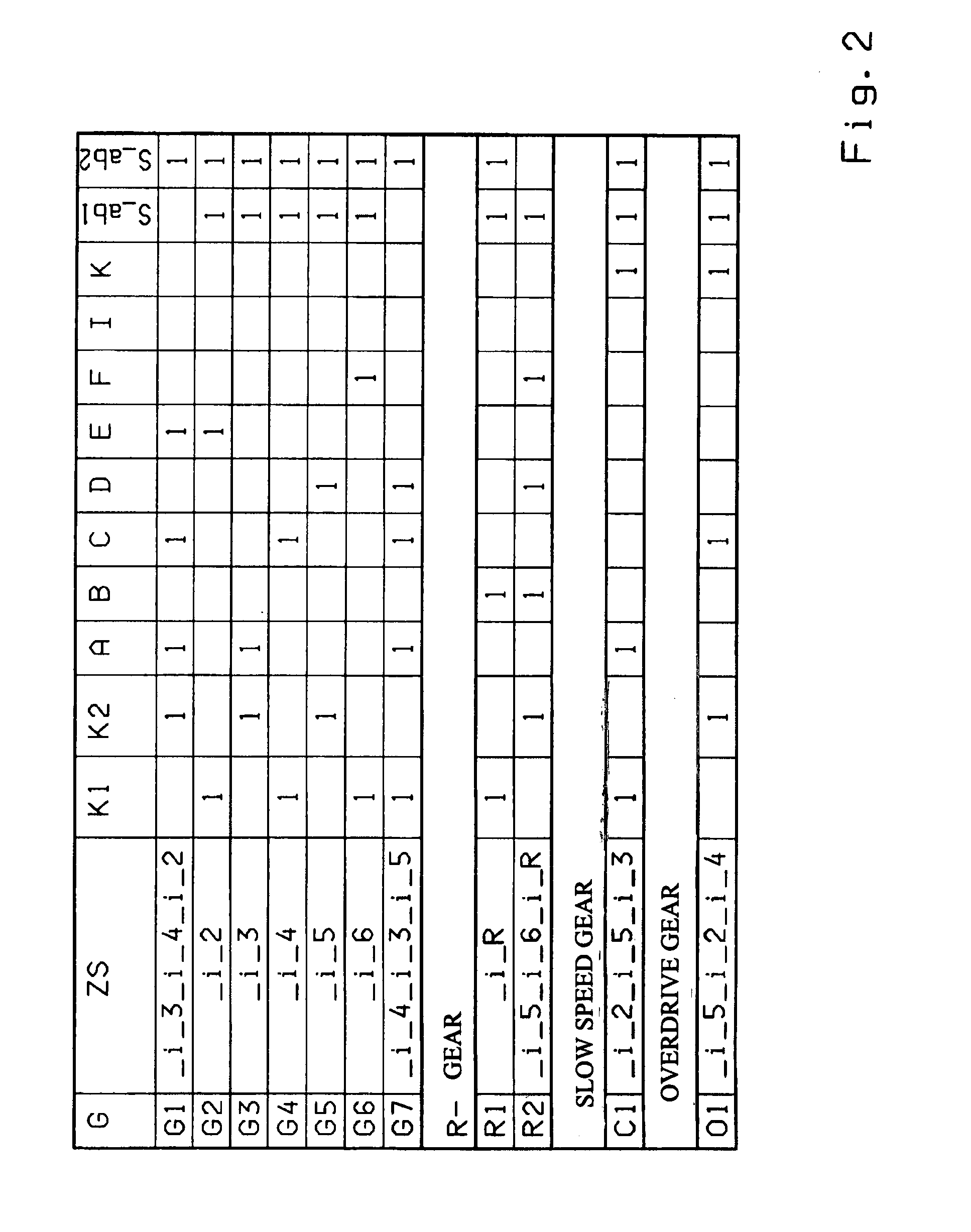
[0042]In the double clutch transmission, in accordance with FIGS. 1 and 2, the output gear wheel 12 is decoupled from the first countershaft w_v1 when the coupling device S_ab1 is disengaged, so that the first forward gear G1 and the seventh forward gear G7 can be shifted as winding-path gears.

second embodiment

[0043]the double clutch transmission, in accordance with FIGS. 3 and 4 illustrates that the output gear wheel 12 is decoupled from the first countershaft w_v1 when the coupling device S_ab1 is disengaged, such that the first forward gear G1 can be shifted as a winding-path gear, and that, at least via one additional shifting device K on the second countershaft w_v2, the idler gear wheel 8 of the second partial transmission is connected with the idler gear wheel 9 of the first partial transmission and, via the shifting device K, the seventh forward gear G7 is shifted as a winding-path gear.

third embodiment

[0044]Also, in the third embodiment, in accordance with FIGS. 5 and 6, the double clutch transmission comprises at least one additional shifting device K on the second countershaft w_k2 and the assigned coupling device S_ab1 which is assigned to the output gear wheel 12. Contrary to the previous embodiments, the first forward gear G1 and the seventh forward gear G7 can be shifted via the shifting device K and a reverse gear R1 can be shifted as a winding-path gear when the coupling device S_ab1 is engaged.


PUM


Abstract

A double clutch transmission with two clutches connected to a drive shaft and to one of two transmission input shafts. Fixed gears are coupled to the input shafts and engage idler gears. Several coupling devices connect the idler gears to a countershaft which have an output gear that couple gears of an output shaft such power shift forward gears and a reverse gear can be shifted. Three dual gear planes each comprising one fixed gear which is supported by an input shaft and two idler gears which are supported by a respective countershaft. In each dual gear plane at least one idler gear wheel can be used for at least two gears such that at least one winding-path gear is engaged by engagement of a disengaged output coupling device assigned to one of the output gear wheels.

Description

[0001]This application is a National Stage completion of PCT / EP2008 / 063427 filed Oct. 8, 2008, which claims priority from German patent application serial no. 10 2007 049 263.6 filed Oct. 15, 2007.FIELD OF THE INVENTION[0002]The present invention relates to a double clutch transmission for a motor vehicle.BACKGROUND OF THE INVENTION[0003]Known from the publication DE 103 05 241 A1 is a 6-speed or 7-speed double clutch transmission. The double clutch transmission comprises two clutches, each connected with their inputs to the drive shaft and their output to one of the two transmission input shafts. The two transmission input shafts are coaxially positioned towards each other. In addition, two countershafts are axially parallel to the transmission input shafts, their idler gear wheels mesh with the fixed gear wheels of the transmission input shafts. Furthermore, coupling devices, that are axially movable, are connected in a rotationally fixed manner to the countershaft to shift the re...

Claims


Application Information

Patent Timeline
IPC IPC(8): F16H3/16
CPCF16H3/006F16H3/093F16H2003/0807F16H2003/0826F16H2003/0931F16H2200/0026Y10T74/19233F16H2200/006F16H2200/0065F16H2200/0086F16H2200/0091Y10T74/19228F16H2200/0056
Inventor GUMPOLTSBERGER, GERHARDWAFZIG, JUERGENREISCH, MATTHIASRIEGER, WOLFGANGDREIBHOLZ, RALF
Owner ZF FRIEDRICHSHAFEN AG
Why Eureka
Try Eureka