Easy Binding Machine

Inactive Publication Date: 2010-08-19
WANG BEI
View PDF11 Cites 2 Cited by
  • Summary
  • Abstract
  • Description
  • Claims
  • Application Information

AI Technical Summary

Benefits of technology

[0004]This invention aims to eliminate the defects in existing binding machines and become a binding machine convenient for use. It can change its auxiliary lacing and auxiliary hook freely and is more convenient to use.
[0013]After adopting the above technical solution, this invention gains advantages in that: since the auxiliary lacing is connected flexibly with the main body, the user can replace auxiliary lacing and auxiliary hook freely according to the actual needs, which makes it more convenient to use.

Problems solved by technology

Since the auxiliary lacing is permanently connected with the binding machine and the auxiliary is permanently linked with the auxiliary lacing, the user cannot change the auxiliary hook according to the actual needs and there is much inconvenience.

Method used


Image

  • Easy Binding Machine
  • Easy Binding Machine
  • Easy Binding Machine

Examples


Embodiment Construction

[0019]The following is a better example to execute this invention, which thus does not restrict the protective scope of this invention.

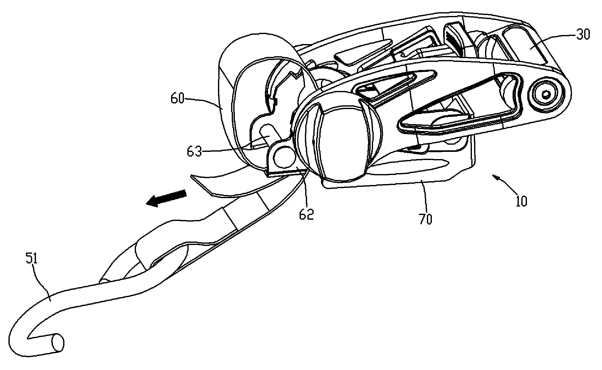
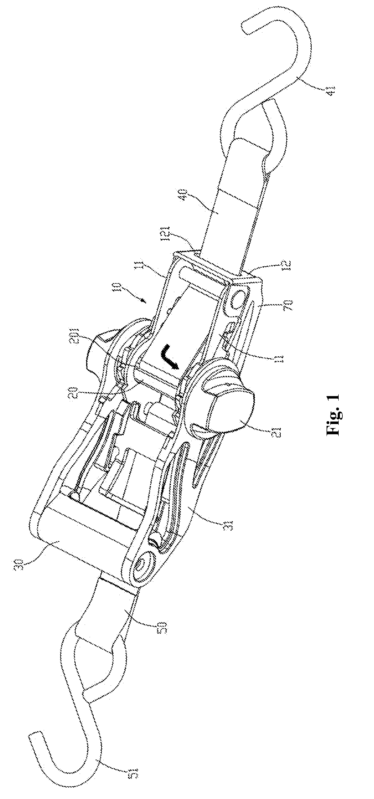
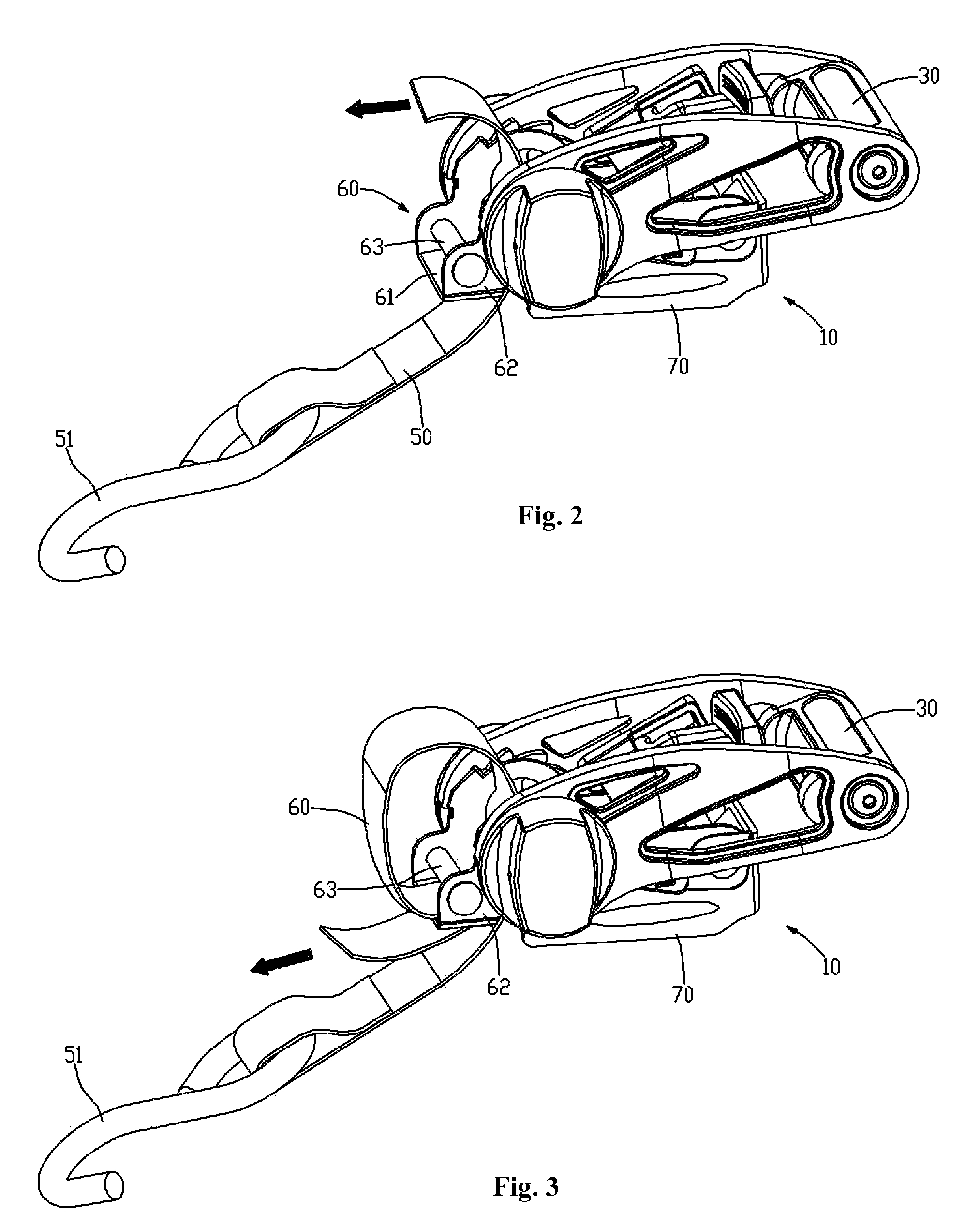
[0020]Please refer to what's shown in attached Drawing 1 to Drawing 4: this invention of binding machine comprises Main Body 10, a Scroll 20, a Handle 30, a Main Lacing 40, an Auxiliary Lacing 50, an Active Buckle 60 and a Non-Slip Mat.

[0021]Main Body 10 is made of steel board, with a level bottom board. The left and right sides of the bottom board curve up to form Side Plate 11. The front end forms Baffle Plate 12 with a leading Groove 121. A hollow cavity is formed between two Side Boards 11 and Baffle Plate 12. In addition, the front section of Main Body 10 is covered with Non-Slip Mat 70 made of soft plastic material in order to prevent scraping the surface of items that are tied by this binding machine. The front section of Main Body 10 is covered with Non-Slip Mat 70 which is made of soft plastic materials.

[0022]Scroll 20 is within the hollow c...


PUM


Abstract

This invention discloses an easy binding machine. It mainly comprises: a main body, a scroll, a handle, a main lacing and an auxiliary lacing. The auxiliary lacing is in the rear side of the main body, and its tail is flexibly connected with the main body. There is an auxiliary hook fixed in the front end. There is an active buckle, which goes with the auxiliary lacing, in the rear of said main body. The said active buckle comprises a bottom board, left and right side walls and pin rolls. The pin roll is fixed between left and right side walls. There is a groove where corresponds to the pin roll in the bottom board. The tail of auxiliary reaches inside the active buckle from downward in the rear of active buckle's bottom board, and then circles the pin roll downward and reaches outside the active buckle through the groove on the bottom board. Since the auxiliary lacing and the main body are flexibly connected, the user can change auxiliary lacing and auxiliary hook freely as per the actual needs, which makes it more convenient to use the binding machine.

Description

CROSS REFERENCE TO THE RELATED PATENT APPLICATION[0001]This patent application claims the priority of the Chinese patent application No. 200920009617.4 filed on Feb. 13, 2009, which application is incorporated herein by reference.FIELD OF THE INVENTION[0002]This invention involves a binding machine, especially one used to tie down the objects, which can fixate and loosen the objects rapidly through rotating the handle.BACKGROUND OF THE INVENTION[0003]The binding machine is widely used in the daily life with various models. One of the binding machines has two lacings, one main lacing with a hook and the other the auxiliary lacing. The main lacing tail, which can be tightened or loosened up by moving the handle, goes round the scroll of the binding machine. The auxiliary lacing is permanently connected with the horizontal beam on the tail section of the binding machine. Since the auxiliary lacing is permanently connected with the binding machine and the auxiliary is permanently linked...

Claims


Application Information

Patent Timeline
IPC IPC(8): B25B25/00
CPCB60P7/083
Inventor WANG, BEI
Owner WANG BEI
Why Eureka
Try Eureka