Power supply control apparatus including overcurrent detection circuit

Inactive Publication Date: 2010-08-19
RENESAS ELECTRONICS CORP
View PDF14 Cites 14 Cited by
  • Summary
  • Abstract
  • Description
  • Claims
  • Application Information

AI Technical Summary

Problems solved by technology

In a system provided with such load and IPD, for example, upon occurrence of an abnormality such as a terminal short circuit in a terminal section of its electronic control system, a wiri

Method used


Image

  • Power supply control apparatus including overcurrent detection circuit
  • Power supply control apparatus including overcurrent detection circuit
  • Power supply control apparatus including overcurrent detection circuit

Examples


first embodiment

of the Present Invention

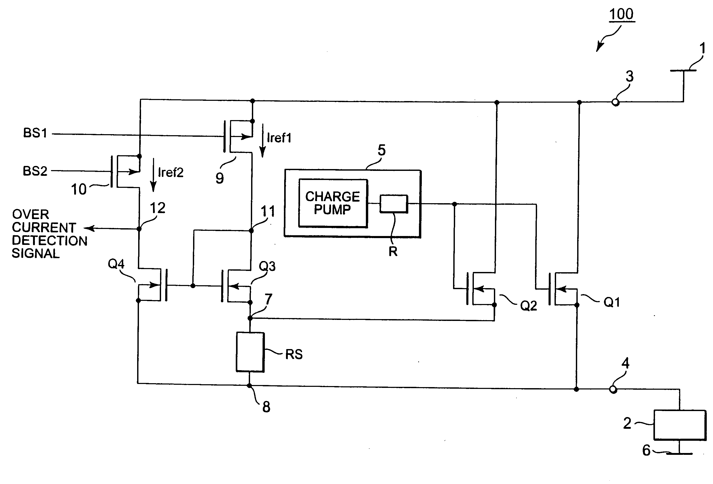
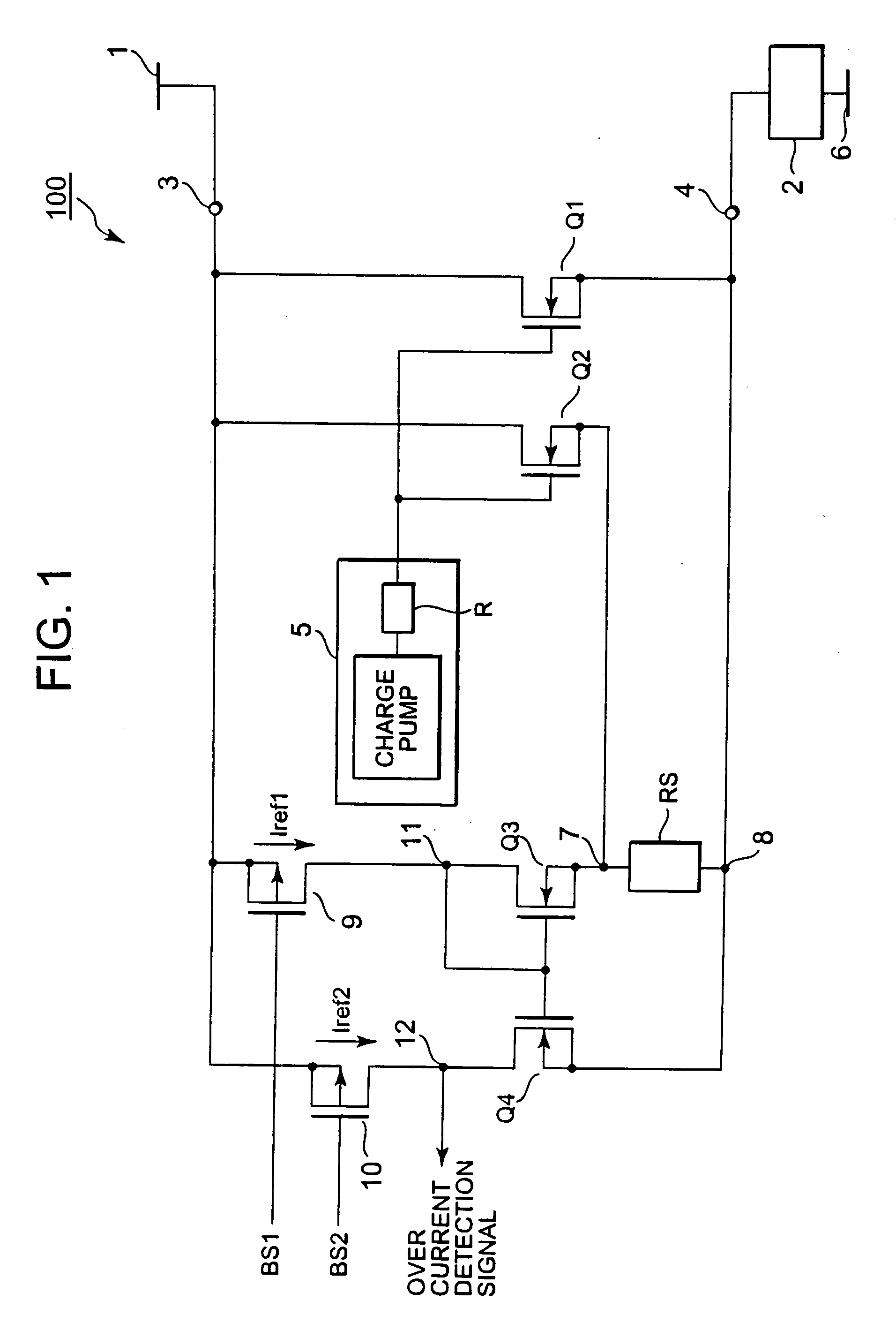
[0026]A first embodiment of the present invention will be described with reference to the drawings. As illustrated in FIG. 1, a power supply control apparatus 100 including an overcurrent detection circuit according to a first embodiment of the present invention is an IPD provided with an overcurrent detection function that protects an output transistor against overcurrent.

[0027]First, the configuration of the circuit illustrated in FIG. 1 will be described. The circuit illustrated in FIG. 1 has a so-called “high-side switch” configuration in which a high-potential-side connection terminal 3 of the power supply control apparatus 100 is connected to a power supply line1 and a load 2 is connected between a low-potential-side connection terminal 4 of the power supply control apparatus 100 and a ground line 6. The power supply control apparatus 100 includes an output MOS transistor (output transistor) Q1, a voltage control circuit 5 and an overcurrent detection c...

second embodiment

of the Present Invention

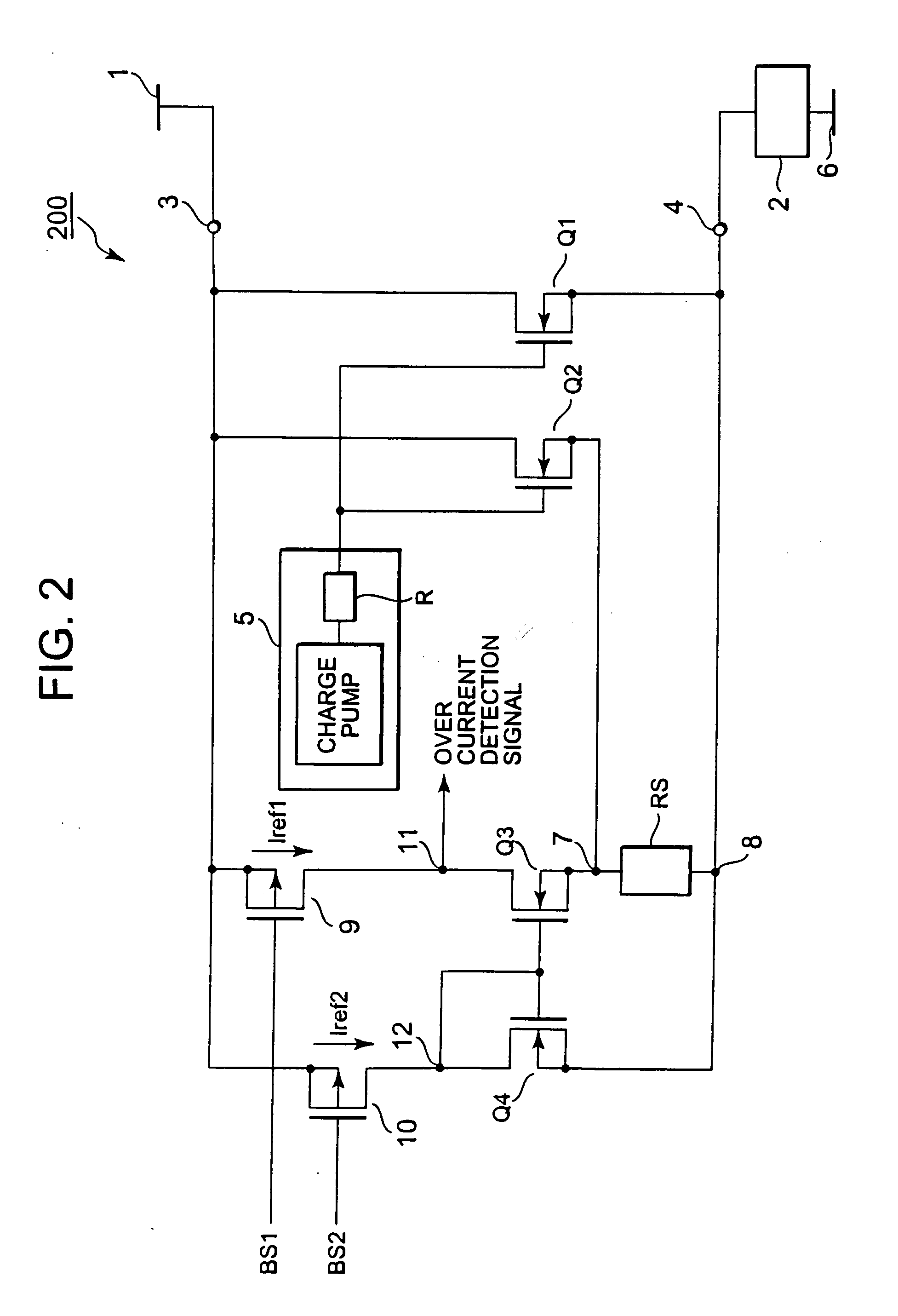
[0048]A second embodiment of the present invention will be described with reference to the drawings. As illustrated in FIG. 2, a power supply control apparatus 200 according to a second embodiment of the present invention is different from the power supply control apparatus 100 illustrated in FIG. 1 in the following points. While in the power supply control apparatus 100, the gate terminals of the transistors Q3 and Q4 are connected to the connecting node 11, in the power supply control apparatus 200, they are connected to a connecting node 12. Also, while in the power supply control apparatus 100, an overcurrent detection signal is output from the connecting node 12, in the power supply control apparatus 200, it is output from a connecting node 11. The rest of the circuit configuration is similar to that of the power supply control apparatus 100, and thus, a description thereof will be omitted.

[0049]Next, an operation of the power supply control apparatus 20...

third embodiment

of the Present Invention

[0053]A third embodiment of the present invention will be described with reference to the drawings. As illustrated in FIG. 3, a power supply control apparatus 300 according to a third embodiment of the present invention is different from the power supply control apparatus 200 illustrated in FIG. 2 in the following points. The circuit illustrated in FIG. 2 has a so-called “high-side switch” configuration in which the load 2 is provided between a low-potential-side connection terminal 4 of the power supply control apparatus 200 and a ground line 6. In contrast, the circuit illustrated in FIG. 3 has a so-called “low-side switch” configuration in which the load 2 is provided between the power supply line 1 and the high-potential-side connection terminal 3 of the power supply control apparatus 300, and the low-potential-side connection terminal 4 of the power supply control apparatus 300 is connected to a ground line 6.

[0054]Further, in the power supply control ap...


PUM


Abstract

Provided is a power supply control apparatus including an overcurrent detection circuit with enhanced overcurrent detection accuracy. A power supply control apparatus according to the present invention includes: an output transistor Q1 that controls a current to be supplied to a load; a voltage control circuit that applies a control voltage to a control terminal of the output transistor Q1; and an overcurrent detection circuit. The overcurrent detection circuit includes: a detection MOS transistor Q2 that generates a detection current according to a current flowing through the output MOS transistor Q1; a transistor 9 that generates a current Iref1 based on a bias signal BS1; a transistor 10 that generates a current Iref2 based on a bias signal BS2 that is different from the bias signal BS1, the transistor 10 having a size that is the same as that of transistor 9; and a current mirror circuit that outputs an overcurrent detection signal based on the current Iref1, the current Iref2 and the detection current. Highly-accurate overcurrent detection can be performed by cancelling the effects of the characteristics variations of the transistors in their manufacturing processes and the characteristic variations of the transistors caused by their surrounding temperature conditions.

Description

CROSS-REFERENCE TO RELATED APPLICATIONS[0001]This application is based upon, claims the benefit of priority of, and incorporates by reference the contents of Japanese Patent Application No. 2009-033669 filed on Feb. 17, 2009.BACKGROUND[0002]1. Field of the Invention[0003]The present invention relates to a power supply control apparatus including an overcurrent detection circuit.[0004]2. Description of Related Art[0005]In recent years, vehicles such as automobiles employ what is called an IPD (Intelligent Power Device), which includes switching elements such as power MOSFETs (Metal-Oxide Semiconductor Field-Effect Transistors) or IGBTs (Insulated Gate Bipolar Transistors), and a control circuit, in their electronic control systems as a power supply control apparatus for a load such as a lamp load or a motor load. In a system provided with such load and IPD, for example, upon occurrence of an abnormality such as a terminal short circuit in a terminal section of its electronic control ...

Claims


Application Information

Patent Timeline
IPC IPC(8): G01R19/00
CPCH03K17/0822H02H3/087
Inventor NAKAHARA, AKIHIRO
Owner RENESAS ELECTRONICS CORP
Why Eureka
Try Eureka