Arrangement and a method for handling failures in a network

a fault handling and network technology, applied in data switching networks, frequency-division multiplexes, instruments, etc., can solve the problems of unsuitable carrier ethernet architecture, unsuitable backbone network and metro network requirements, and high requirements for snmp based solutions, etc., to achieve fast and simple fault detection and localization, fast and efficient fault recovery, and the effect of ethernet based carrier or access network deployment is very advantageous and attractiv

Active Publication Date: 2010-08-19
TELEFON AB LM ERICSSON (PUBL)
View PDF3 Cites 64 Cited by
  • Summary
  • Abstract
  • Description
  • Claims
  • Application Information

AI Technical Summary

Benefits of technology

[0016]It is an advantage of the invention that a fast and simple fault detection and localization is enabled. It is also an advantage that the message overhead, i.e. the number of messages that need to be sent in order to localize a fault, is considerably reduced as compared to known methods. I

Problems solved by technology

However, backbone networks and metro networks have requirements which differ quite a lot from those of enterprise LANs.
It is however a disadvantage that SNMP based solutions are extremely slow which makes them unsuitable for carrier Ethernet architectures.
However, it suffers from disadvantages and limitations which make the performance non-optimal.
Due to the fact that 802.1ag aims at a solution for end-to-end service provisioning in a very general scope it is actually a very flexible solution and therefore it is not optimized as far as rate and performance is concerned.
Further 802.1ag uses STP or RSTP to find out an alternative path when a failure occurs, but STP as well as RSTP can have a

Method used


Image

  • Arrangement and a method for handling failures in a network
  • Arrangement and a method for handling failures in a network
  • Arrangement and a method for handling failures in a network

Examples


Embodiment Construction

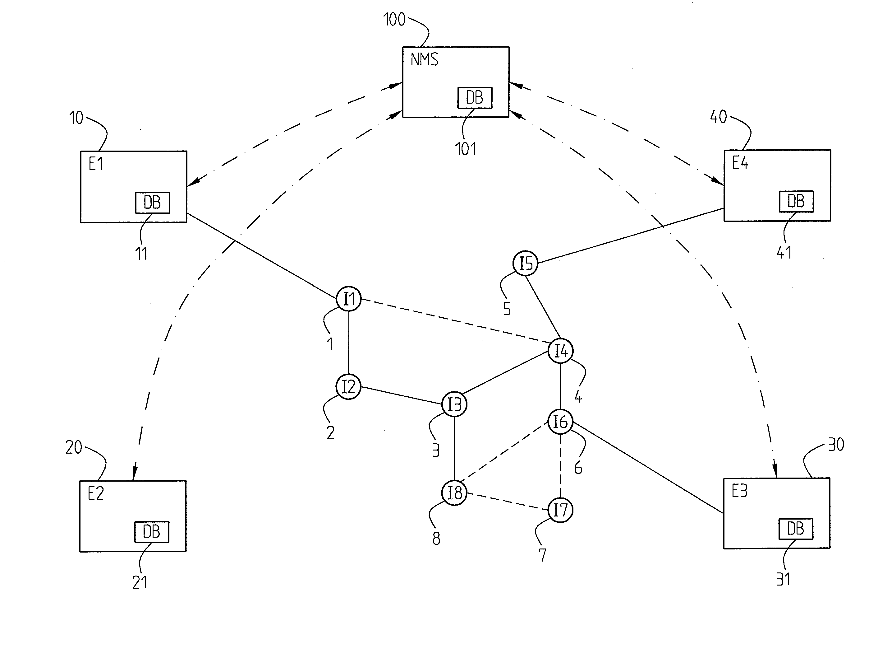
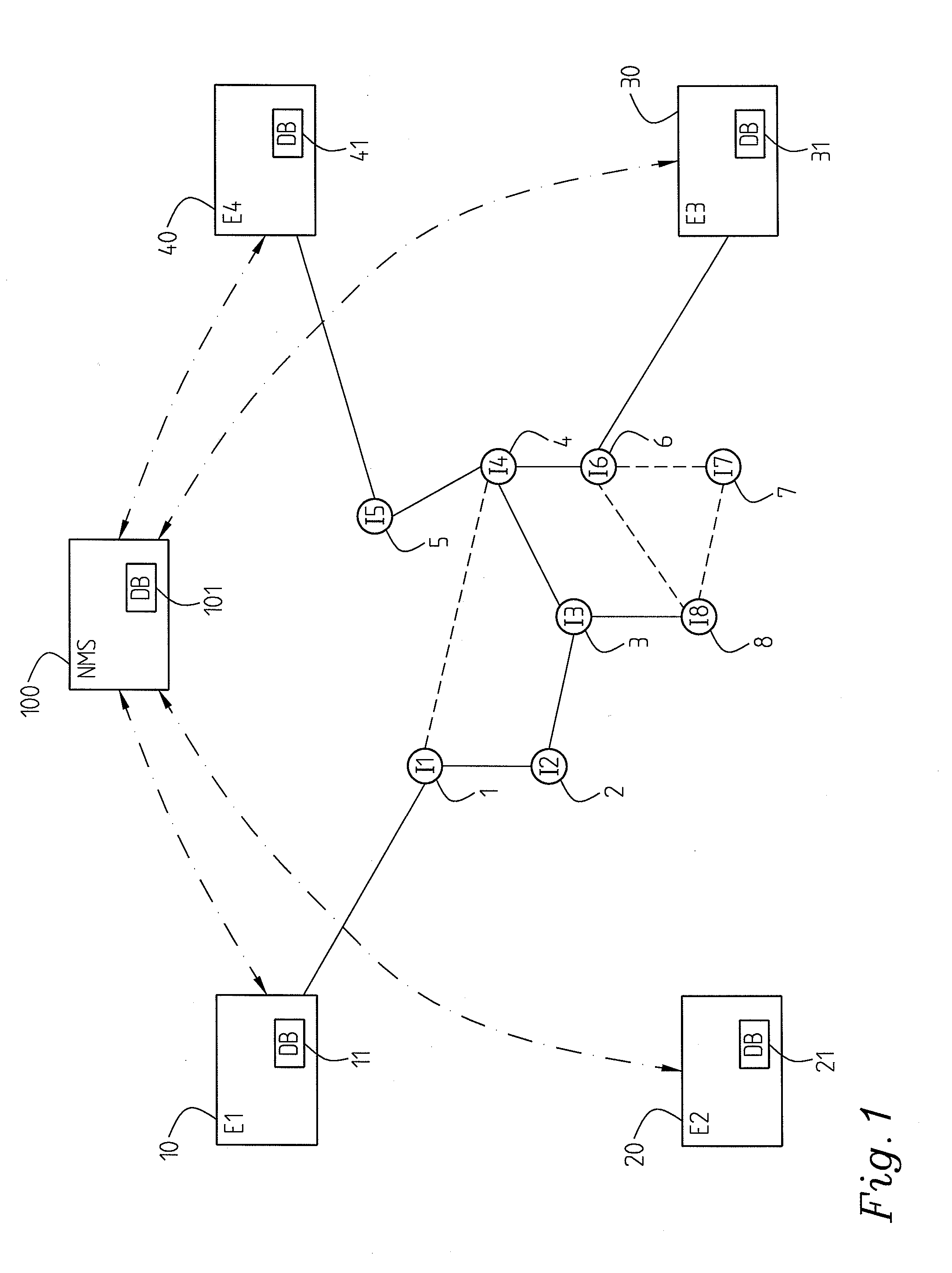
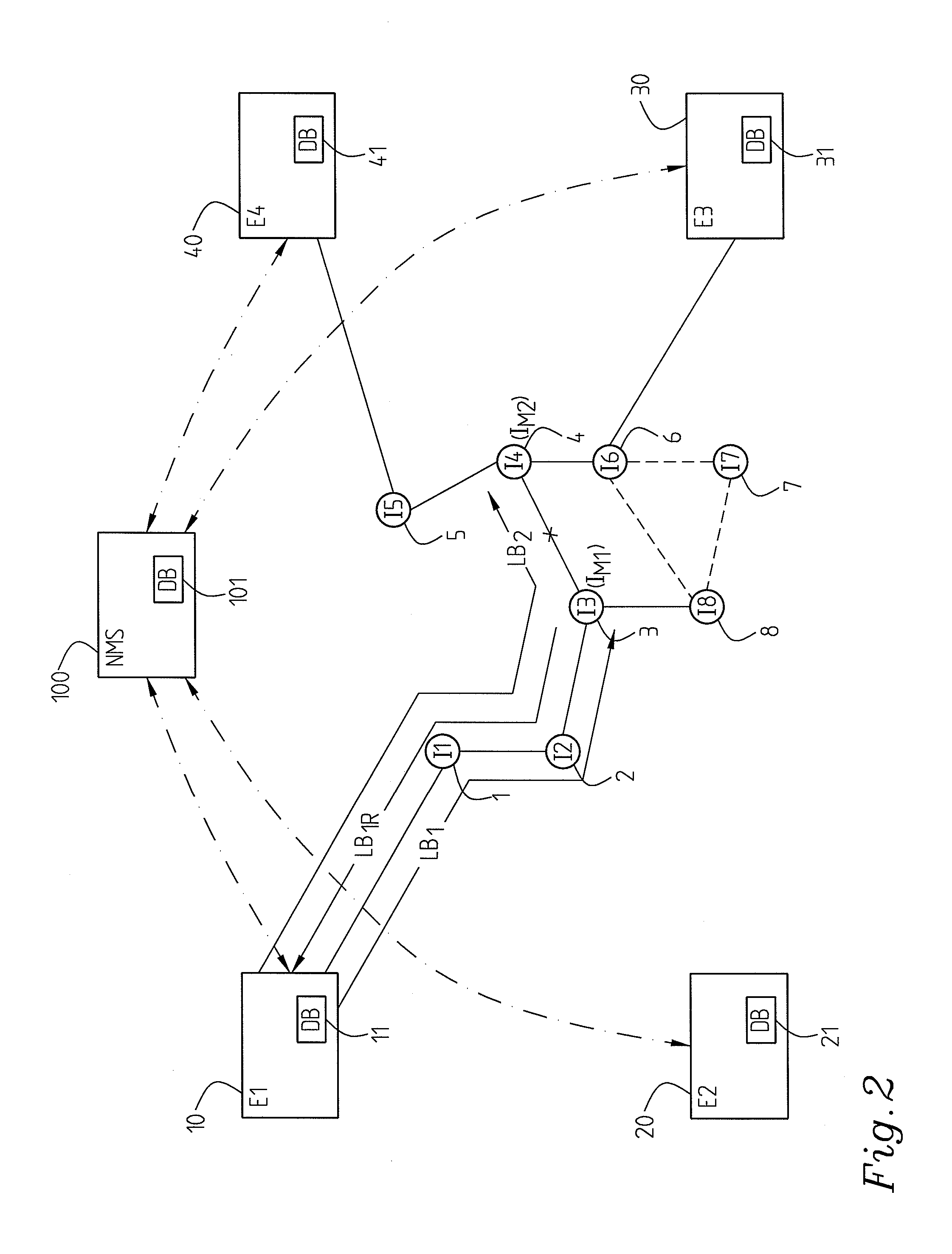
[0025]In a particular embodiment, cf. FIG. 1, FIG. 2 of the invention an edge node 10 is adapted to report fault information of a localized fault to the network management system 100. However, preferably it is not dependent on any reaction on behalf of the management system, but capable to handle temporary recovery itself or independently of the network management system.

[0026]Optionally an edge node 10; 20; 30; 40; 50; 60 is adapted to handle detection and localization of faults on nodes and links. Particularly it is capable of distinguishing between node faults and link faults (failures). Alternatively it is merely capable of identifying a fault, the fault being either on a node or on a link connecting to the node.

[0027]In an advantageous implementation connectivity check messages (CCM) are implemented for the detection of faults. In one embodiment this e.g. means that an edge node 10; 20; 30; 40; 50; 60 is adapted to periodically send such CCM messages to all other edge nodes or ...


PUM


Abstract

The present invention relates to an arrangement comprising an Ethernet carrier network, managed by a management system (100) and comprising a number of levels of management domains, each comprising a number of edge nodes (10, 20, 30, 40) and a number of intermediate nodes (1, 2, 3, 4, 5, 6, 7, 8). Each edge node (10, 20, 30, 40) comprises fault detection of connectivity check messages and fault locating means with holding means (11, 21, 31, 41) adapted to hold path information for the paths to all other edge nodes. A fault detection means of an edge node having detected a fault is adapted to activate edge node fault locating means to locate the fault using the patch information in the edge node holding means to find a first target intermediate node substantially in the middle of the path containing the fault, and to, directly, send a first loop back message to said intermediate node. A response from said intermediate node indicates that the fault is located at the distant portion of the path, no response indicates that the fault is located at the proximate portion of the path. Further loop back messages are sent to consecutively identified intermediate nodes of the respective path portion identified to contain the fault by the respective preceding loop back message until the fault is localized.

Description

TECHNICAL FIELD[0001]The present invention relates to fault handling in Ethernet network which is managed by a management system and which comprises a number of levels of management domains.STATE OF THE ART[0002]Ethernet is one of the most important Local Area Network (LAN) technologies. Actually it is the leading LAN technology. This is mainly due to a plurality of intrinsic characteristics of the technology which makes it simple, cheap and easy to manage and in addition thereto backwards compatible. Operators and carriers are considering the possibility of reaping the benefits of Ethernet by replacing SONET / SDH SSynchronous Digital Hierarchy) infrastructures with Ethernet infrastructures since data services account for the bulk of traffic. However, backbone networks and metro networks have requirements which differ quite a lot from those of enterprise LANs. Consequently a deployment of Ethernet technology would require specific enhancements and several modifications in order to be...

Claims


Application Information

Patent Timeline
IPC IPC(8): H04L12/24H04L41/0213H04L41/0654H04L41/0659H04L41/0677H04L43/0811H04L43/10H04L45/00H04L69/40
CPCH04L41/0213H04L41/0659H04L41/0672H04L41/0677H04L69/40H04L43/10H04L45/26H04L45/66H04L43/0811H04L41/0661
Inventor ZHAO, WEIKOLHI, JOHAN
Owner TELEFON AB LM ERICSSON (PUBL)
Why Eureka
Try Eureka