Safety and guide type brewing kettle

Inactive Publication Date: 2010-08-26
TIEN JUNG JUNG
View PDF17 Cites 40 Cited by
  • Summary
  • Abstract
  • Description
  • Claims
  • Application Information

AI Technical Summary

Benefits of technology

[0011]An objective of the present invention is to provide a safety and guide type brewing kettle, which, structurally, is composed of a kettle body having a bottom forming a through bore. The kettle body has a lower circumference from which a projecting wall projects. The kettle body is pivotally connected to a cover. A water stopper is movably received in the kettle body. A screen filter is arranged inside and close to the bottom of the kettle body. A retention disk is mounted under the kettle body through a movable structure and is movable with respect to the kettle body in a vertical direction. The cover forms a flow guide plate, which guides liquid droplets formed on the cover into the kettle body. The through bore of the kettle body receives therein a plug, which forms a through hole havin

Problems solved by technology

When the cover 91 is opened, due to no liquid flow guide means provided on the cover 91, the droplets on the cover 91 will flow along the kettle body 90 and the handle 92 and thus splash to a fixture surface on which the brewing device is placed, leading to poor cleanliness.
(2) The conventional liquid brewing device comprises a filter that is difficult to mount and dismount.
Further, the conventional filter is not provided with a vent hole, so that no air interchange is allowed, making the discharge of the brewing liquid very difficult.
The retention disk has at least a portion that is not enclosed and shielded, so that that portion may be unexpectedly contacted by a user, causing liquid leaking through a liquid dispensing structure.
The legs function to support the cup, but the area defined among the support points formed by the legs is smaller than a projection area of the retention disk, so that the cup may tip easily when placed on a fixture surface, leading to poor stability and safety.
Further, the legs extending through the retention disk makes the manufacturing and assembling difficult.
ZL97116221.2 and Taiwan Patent Publication No. 351

Method used


Image

  • Safety and guide type brewing kettle
  • Safety and guide type brewing kettle
  • Safety and guide type brewing kettle

Examples


Embodiment Construction

[0031]The following descriptions are exemplary embodiments only, and are not intended to limit the scope, applicability or configuration of the invention in any way. Rather, the following description provides a convenient illustration for implementing exemplary embodiments of the invention. Various changes to the described embodiments may be made in the function and arrangement of the elements described without departing from the scope of the invention as set forth in the appended claims.

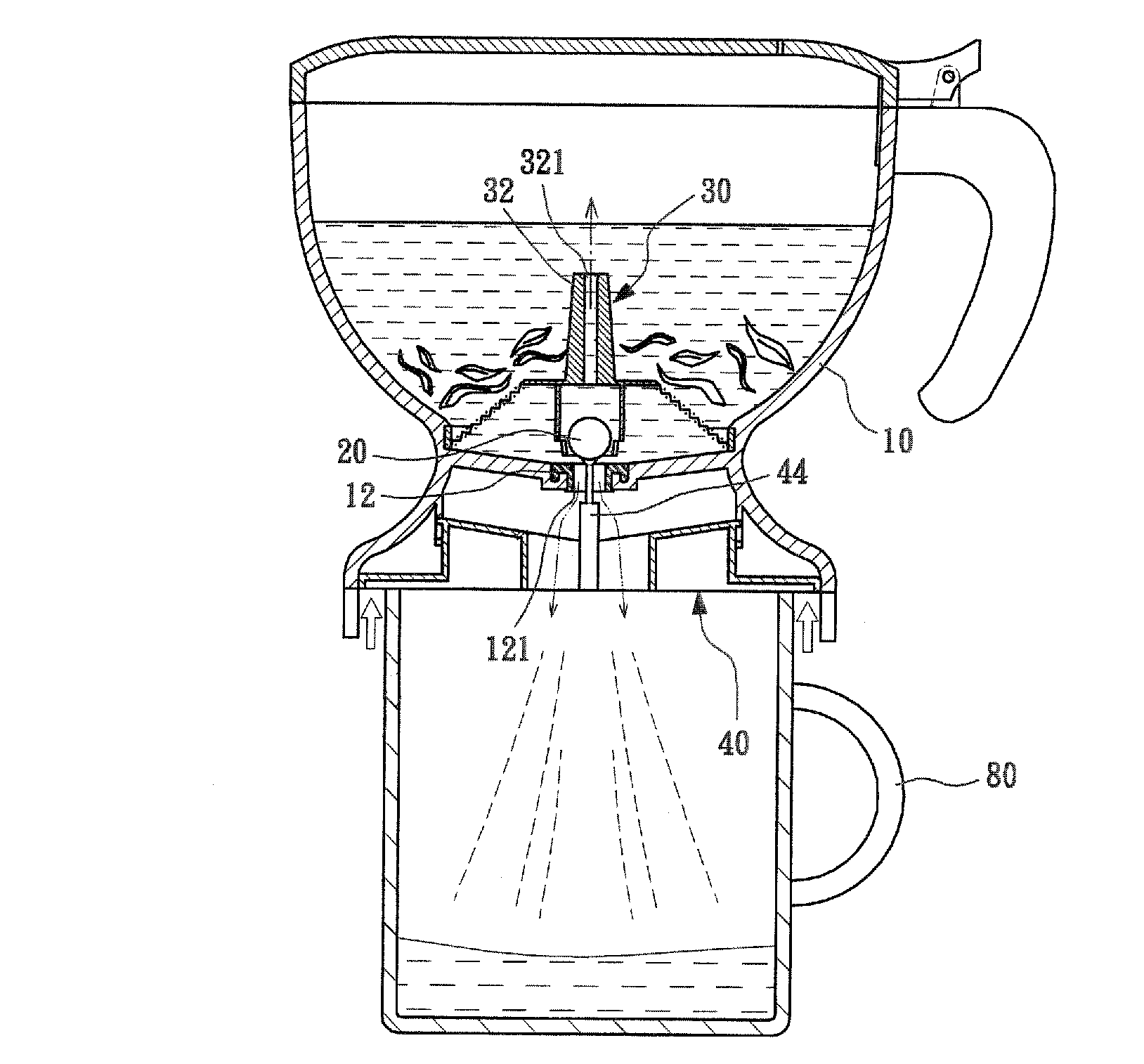
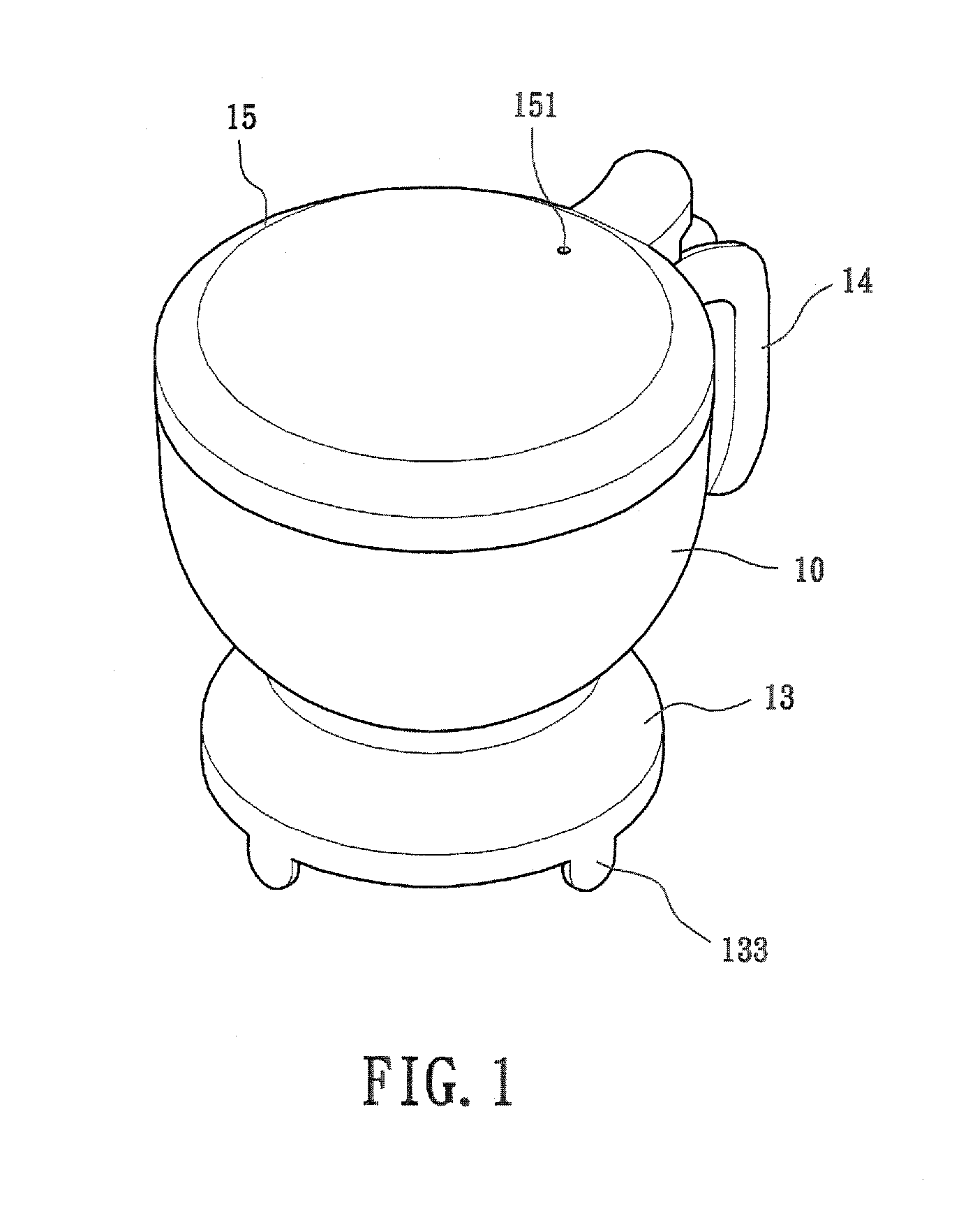
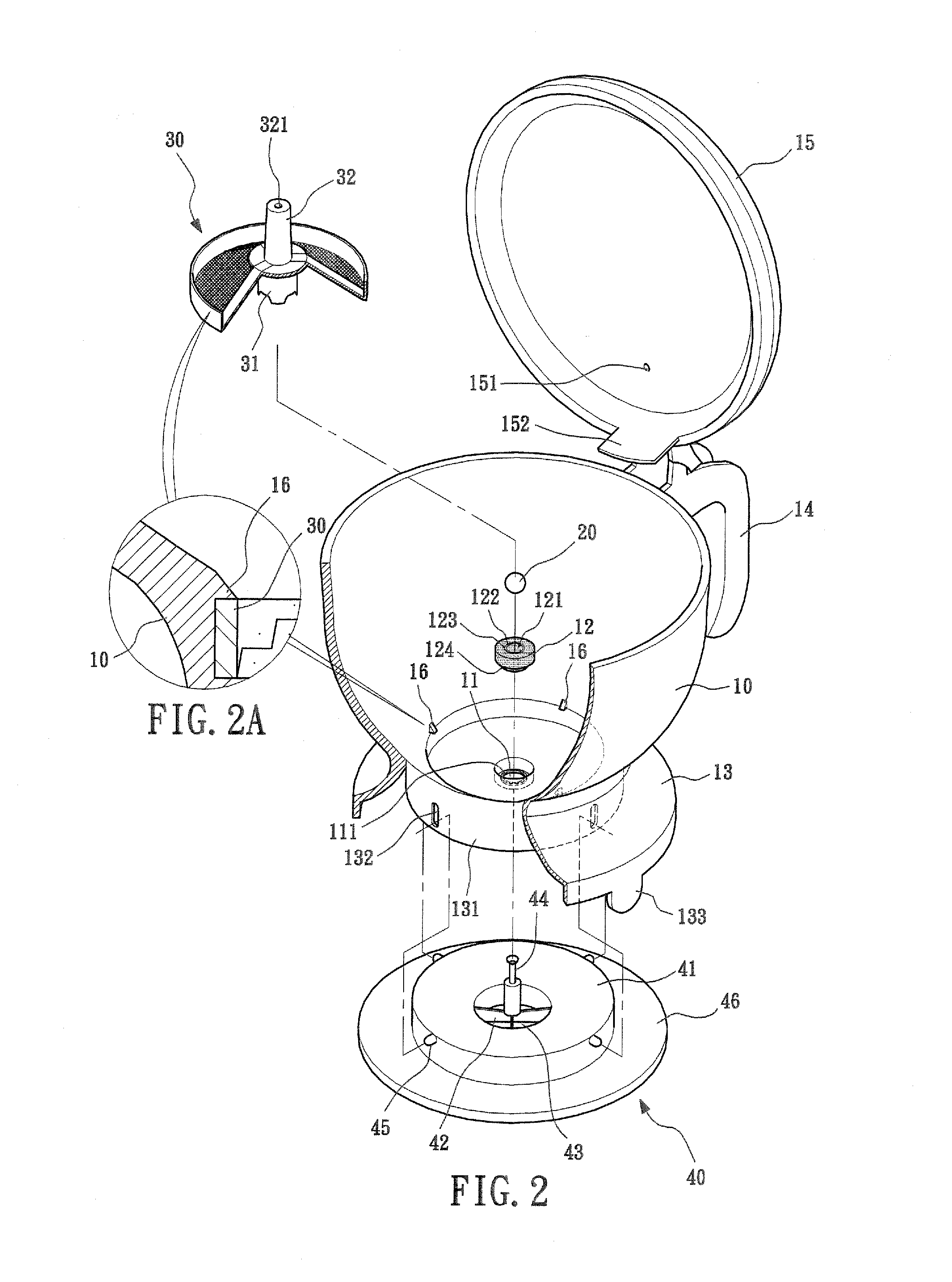
[0032]Referring to FIGS. 1, 2, and 3, the present invention provides a brewing kettle comprising a kettle body 10, a water stopper 20, a screen filter 30, and a retention disk 40, which will be described in detailed.

[0033]The kettle body 10 forms a receiving space for receiving therein for example coffee powders, tea leaves, or other articles to be brewed. The kettle body 10 has a bottom forming a through bore 11 and a circumferential rim 111 along a circumference of the through bore 11. The inner b...


PUM


Abstract

A safety and guide type brewing kettle includes a kettle body, a water stopper, a screen filter, and a retention disk. The kettle body has a cove that forms a flow guide plate for guiding liquid droplets formed on the cover into the kettle body. The kettle body has a bottom forming a through bore that receives therein a plug, which forms a through hole and an engagement section. The water stopper is arranged to block the through hole for eliminating undesired leaking. The kettle body has a lower circumference forming a projecting wall that forms legs to enclose and stably hold the kettle body. The kettle body forms at least one locking section, which engages an upper side of the screen filter. The screen filter forms a grip section that facilitates assembling/disassembling and cleaning. The screen filter forms a positioning section for positioning the water stopper.

Description

TECHNICAL FIELD OF THE INVENTION[0001]The present invention generally relates to a safety and guide type brewing kettle.DESCRIPTION OF THE PRIOR ART[0002]A conventional liquid brewing device has several disadvantages as follows:[0003](1) As shown in FIG. 11 of the attached drawings, a conventional liquid brewing device comprises a kettle body 90 that comprises a cover 91 pivotally connected to a handle 92 mounted to one side of the kettle body 90. When the cover 91 is in a closed condition, vapors of the liquid used to brew objects to be brewed goes upward and droplets are formed on an inside surface of the cove 91. When the cover 91 is opened, due to no liquid flow guide means provided on the cover 91, the droplets on the cover 91 will flow along the kettle body 90 and the handle 92 and thus splash to a fixture surface on which the brewing device is placed, leading to poor cleanliness.[0004](2) The conventional liquid brewing device comprises a filter that is difficult to mount and...

Claims


Application Information

Patent Timeline
IPC IPC(8): A47J31/10A47J31/18
CPCA47J31/0626A47J31/0605
Inventor TIEN, PAO-WULIN, YU-MEI TIEN
Owner TIEN JUNG JUNG
Why Eureka
Try Eureka