Method for producing liquid ejecting head, liquid ejecting head, and liquid ejecting device

Active Publication Date: 2010-08-26
SEIKO EPSON CORP
View PDF2 Cites 0 Cited by
  • Summary
  • Abstract
  • Description
  • Claims
  • Application Information

AI Technical Summary

Benefits of technology

[0021]In such an aspect, a liquid ejecting device excel

Problems solved by technology

Therefore, a high energy is required to increase the cost and also the application of a high electric field has had a possibility of deterioration, breakage, or the like of the piezoelectric layer.
Such problems are not limited to ink jet recording head

Method used


Image

  • Method for producing liquid ejecting head, liquid ejecting head, and liquid ejecting device
  • Method for producing liquid ejecting head, liquid ejecting head, and liquid ejecting device
  • Method for producing liquid ejecting head, liquid ejecting head, and liquid ejecting device

Examples


Example

First Embodiment

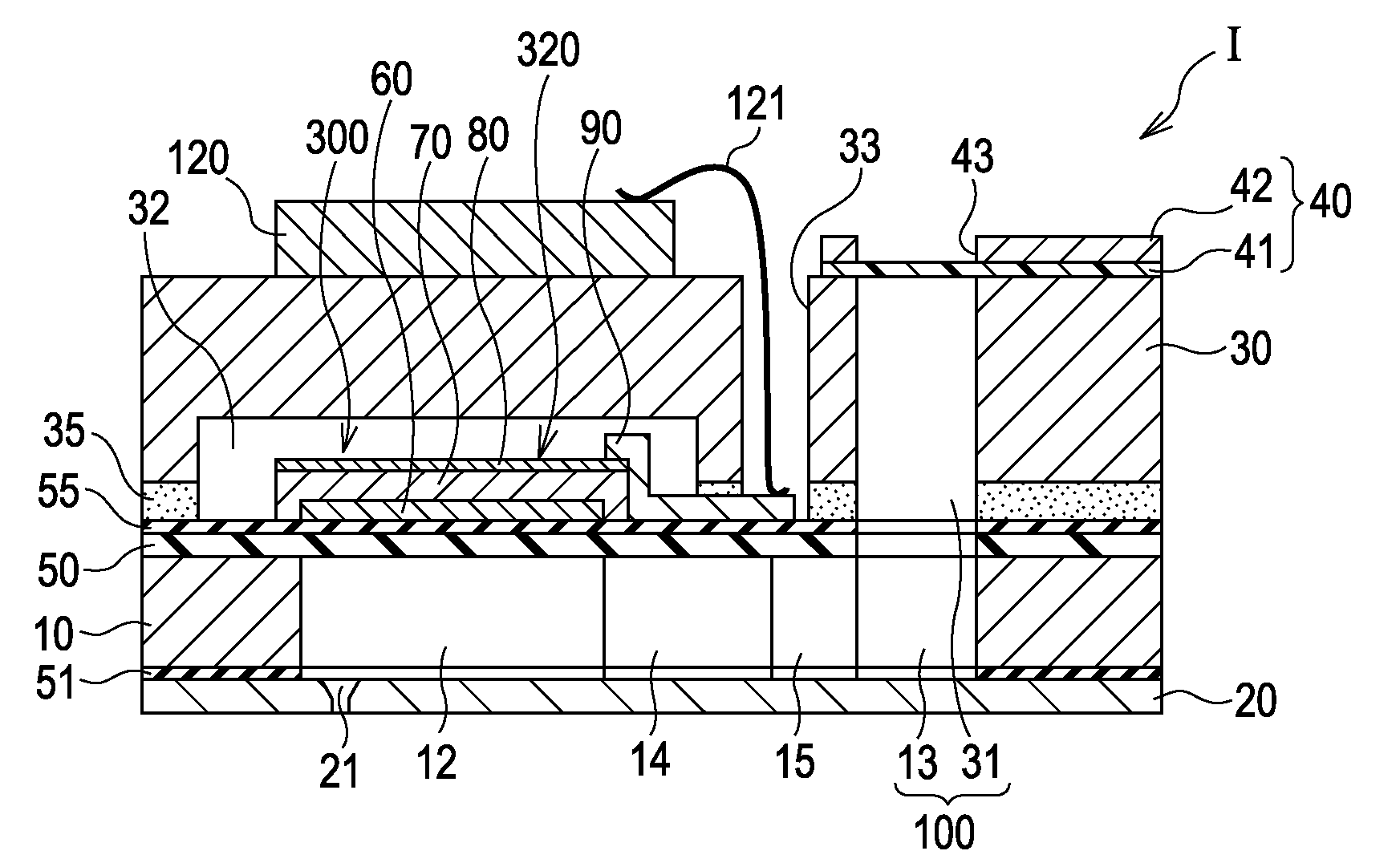
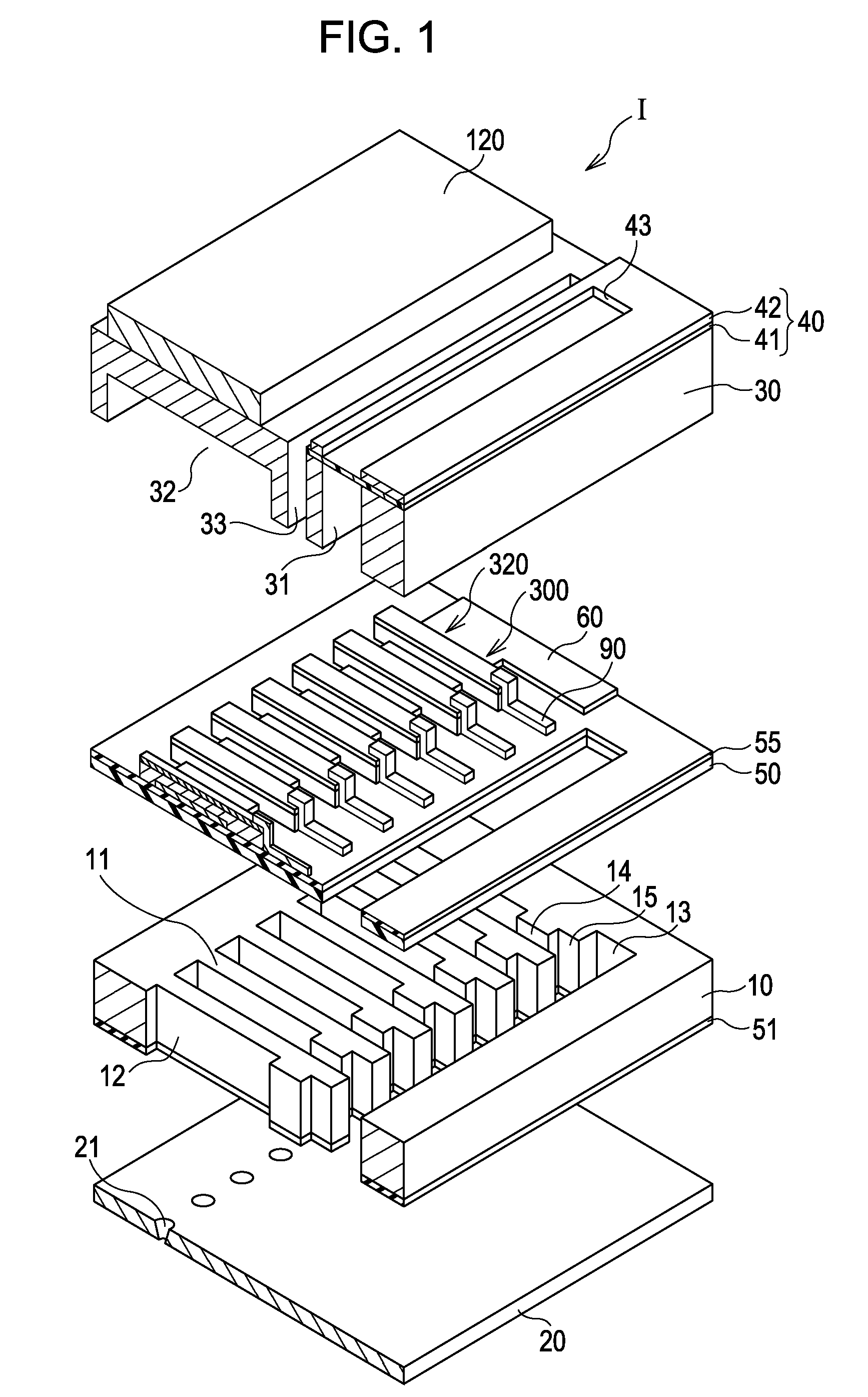
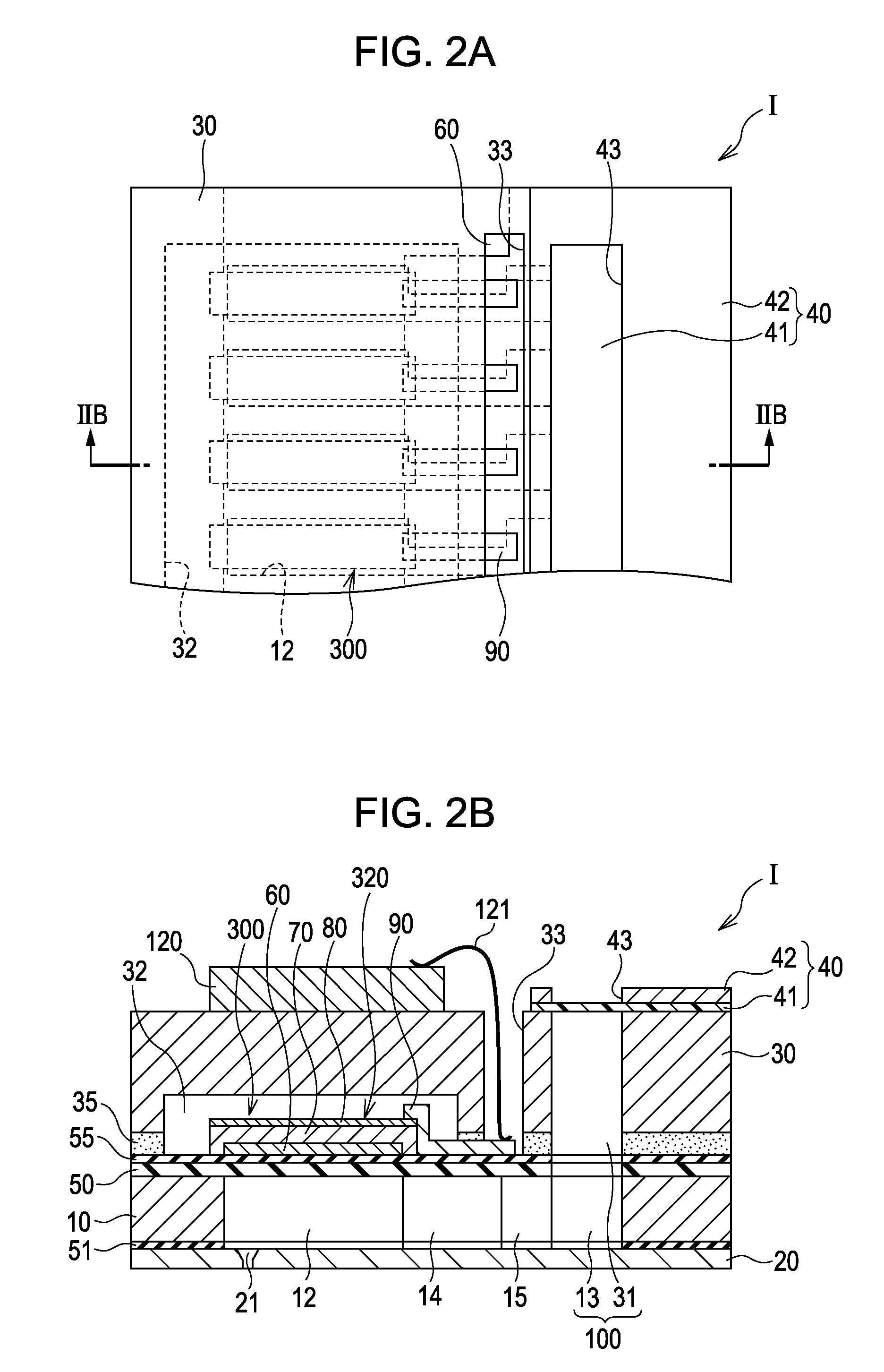
[0041]FIG. 1 is an exploded perspective view illustrating the schematic structure of an ink jet recording head as an example of a liquid ejecting head according to a first embodiment of the invention. FIG. 2A is a plan view of a flow path forming substrate and FIG. 2B is a cross sectional view along the IIB-IIB line of FIG. 2A.

[0042]As shown in the figures, in this embodiment, a flow path forming substrate 10 contains a silicon single crystal substrate and, on one side thereof, an elastic film 50 containing silicon dioxide as a main component is formed.

[0043]The flow path forming substrate 10 is provided with a plurality of pressure generating chambers 12 arranged side by side in the width direction. A communicating portion 13 is formed in a region on the outside in the longitudinal direction of the pressure generating chambers 12 of the flow path forming substrate 10. The communicating portion 13 and each pressure generating chamber 12 are communicated with each oth...


PUM

PropertyMeasurementUnit
Lattice constantaaaaaaaaaa
Pressureaaaaaaaaaa
Piezoelectricityaaaaaaaaaa

Abstract

A liquid ejecting head has a piezoelectric element with a first electrode, a piezoelectric layer, and a second electrode. The liquid ejecting head causes pressure changes in a pressure generating chamber communicating with a nozzle opening. The piezoelectric layer has a perovskite structure and is preferentially orientated in a (100) plane. A method for producing the liquid ejecting head includes polarizing the piezoelectric layer by applying an electric field having energy higher than energy required for converting the polarization direction in the <111> direction to the <110> direction and lower than energy required for converting the polarization direction in the <111> direction to the <001> direction when the electric field to be applied to the piezoelectric layer is in the <001> direction vertical to a plane on which the second electrode is provided.

Description

CROSS-REFERENCE TO RELATED APPLICATIONS[0001]This application claims the benefit of priority to Japanese Patent Application No. 2009-041563 filed Feb. 24, 2009, and Japanese Patent Application No. 2009-221560 filed Sep. 25, 2009, the contents of which are hereby incorporated by reference in their entirety.BACKGROUND[0002]1. Technical Field[0003]The present invention relates to a method for producing a liquid ejecting head provided with a piezoelectric element having a first electrode, a piezoelectric layer, and a second electrode, a liquid ejecting head, and a liquid ejecting device.[0004]2. Related Art[0005]A piezoelectric element for use in liquid ejecting heads, such as an ink jet recording head, is an element in which a piezoelectric layer containing a piezoelectric material showing an electromechanical conversion function is interposed between two electrodes. As the piezoelectric layer, a piezoelectric layer containing lead, zirconium, and titanium, such a piezoelectric layer u...

Claims


Application Information

Patent Timeline
IPC IPC(8): B41J2/045H04R17/00H01L41/083H01L41/047H01L41/09H01L41/18H01L41/187H01L41/22H01L41/257
CPCB41J2/161B41J2/1628B41J2/1642Y10T29/42B41J2002/14241B41J2002/14419B41J2/1646
Inventor MIYAZAWA, HIROMU
Owner SEIKO EPSON CORP
Why Eureka
Try Eureka