
Liquid Crystal Display Device

a display device and liquid crystal technology, applied in static indicating devices, instruments, non-linear optics, etc., can solve the problems of complicated control and increase in cost, and achieve the effect of reducing size and cos

Inactive Publication Date: 2010-08-26
ROHM CO LTD
View PDF3 Cites 2 Cited by
  • Summary
  • Abstract
  • Description
  • Claims
  • Application Information

AI Technical Summary

Benefits of technology

The present invention provides a liquid crystal display device that can achieve color display without applying voltages of different levels, which reduces size and cost. The device includes a plurality of pixels arranged in a matrix, with first electrodes and second electrodes. A liquid crystal layer is arranged between the electrodes, and color filters directly or indirectly covering the electrodes. A driver supplies image display signals to the electrodes to selectively display an image. The number of pixels in the first direction is larger than the number of pixels in the second direction, and each pixel corresponds to a predetermined number of adjacent electrodes. The device can display a color image including a desired number of colors. The first electrodes are connected to the scanning signal supply terminals of the driver via a plurality of first wirings, while the second electrodes are connected to the control signal supply terminals of the driver via a plurality of second wirings. The driver may be in the form of an elongated rectangle, and the scanning signal supply terminal and the control signal supply terminal are provided at a longer side of the driver.

Problems solved by technology

Moreover, to achieve the full-color display, the driver to drive the liquid crystal display device needs to apply voltages of different levels to the second electrodes 92R, 92G, 92B, which requires complicated control.
Thus, the use of a driver with a high function and the accompanying increase in size are necessary, which leads to an increase in the cost.

Method used


Image

  • Liquid Crystal Display Device
  • Liquid Crystal Display Device
  • Liquid Crystal Display Device

Examples


first embodiment

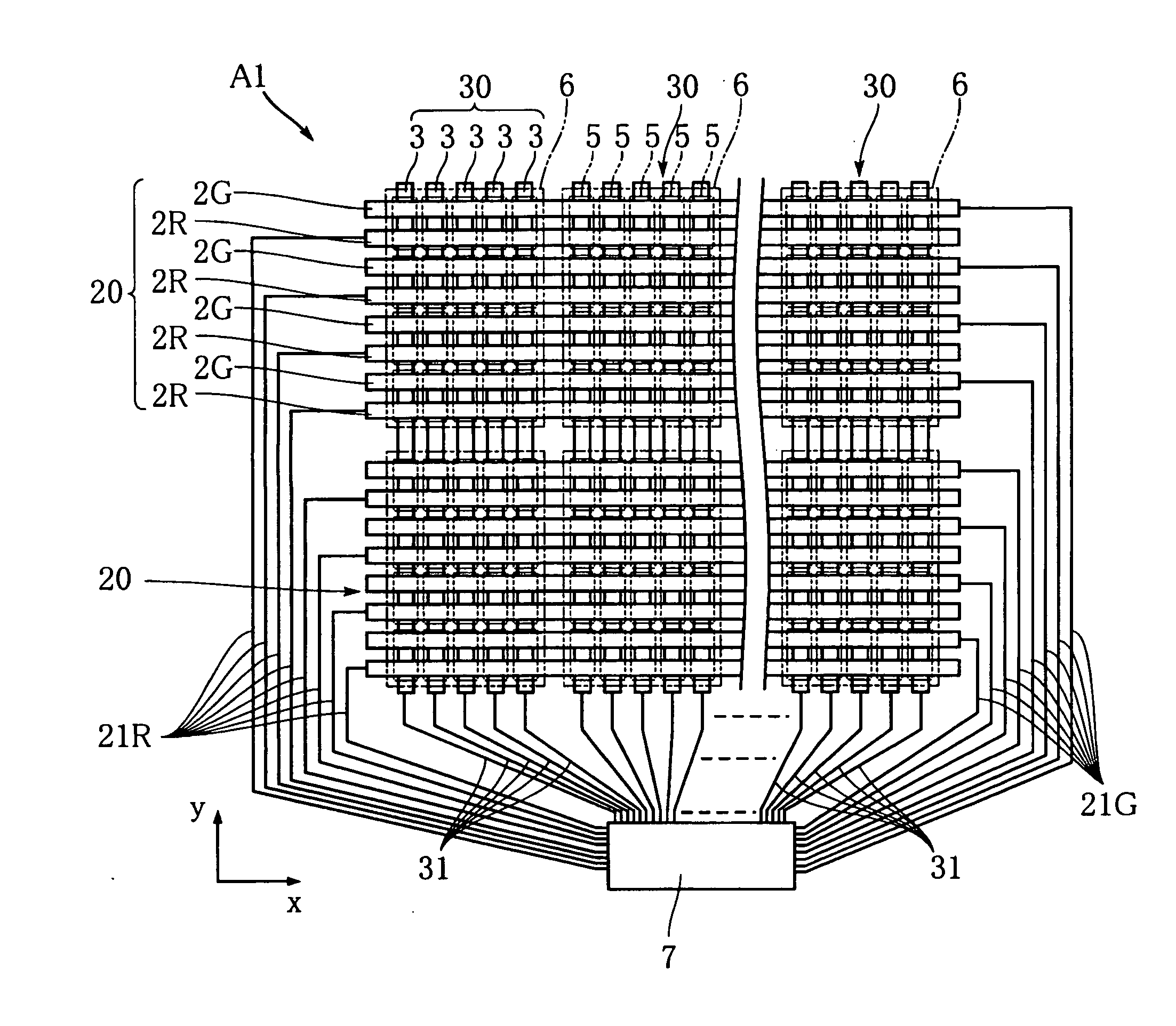
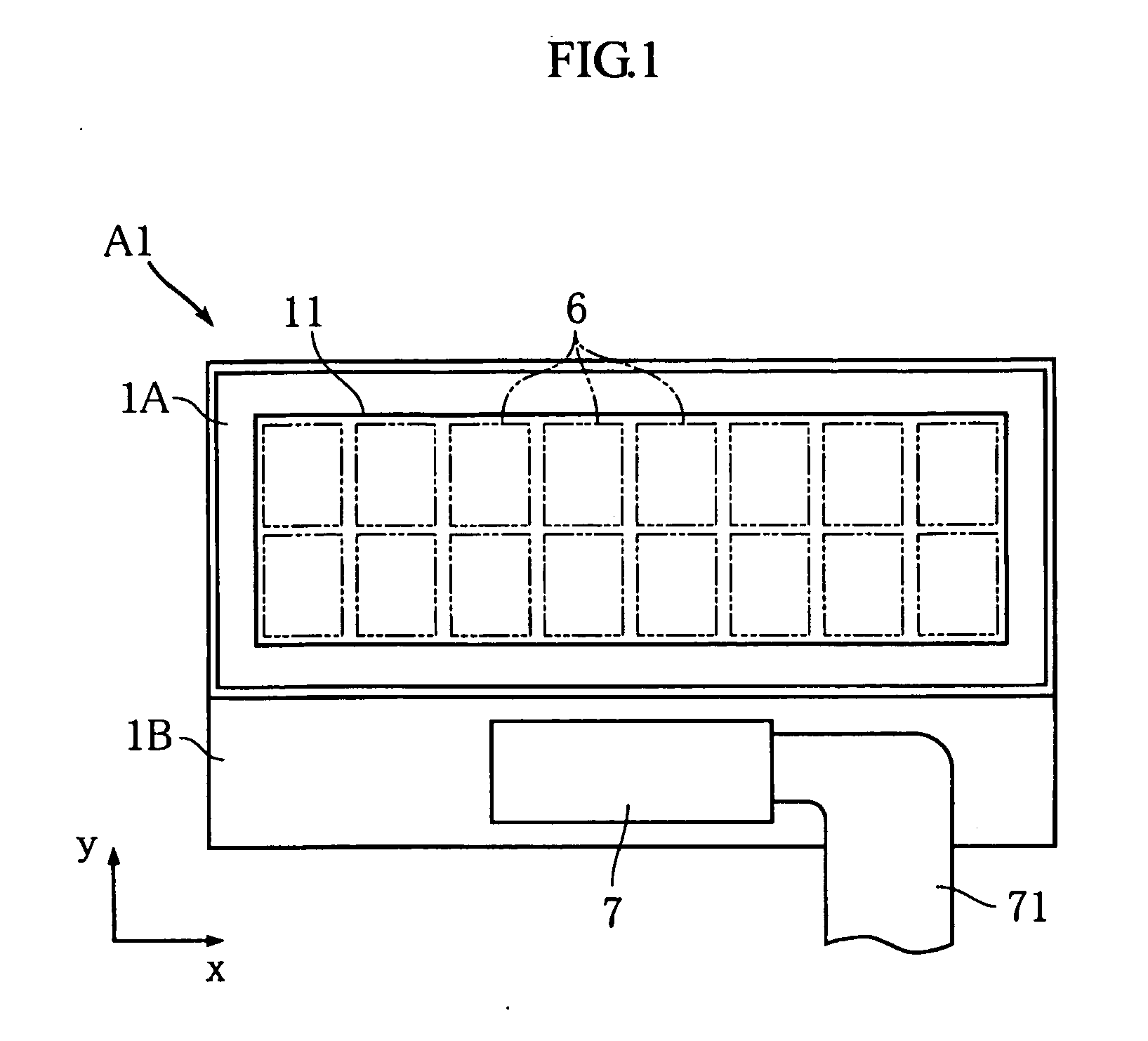
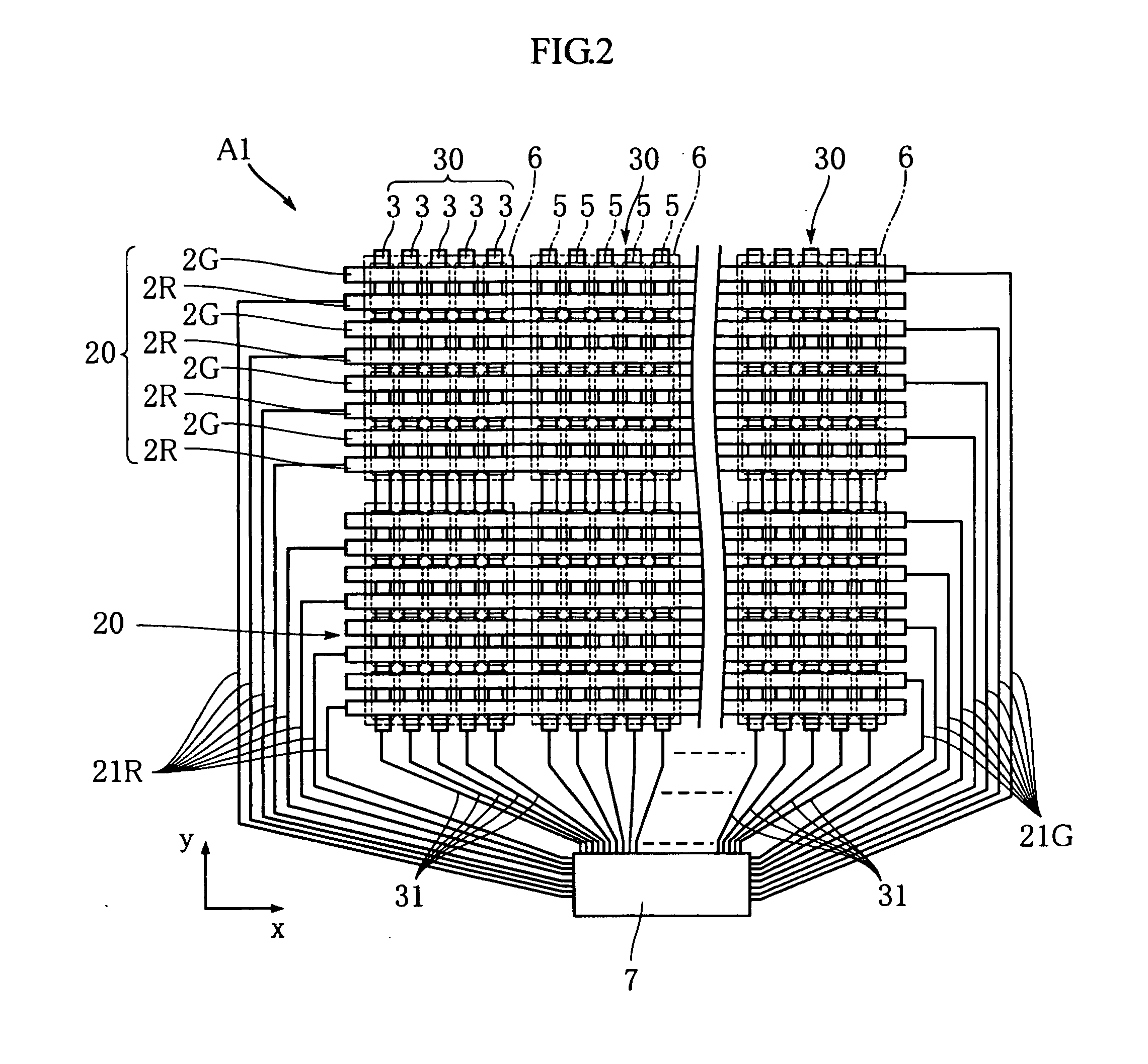
[0024]FIGS. 1-4 show a liquid crystal display device A1 according to the present invention. The liquid crystal display device A1 of this embodiment includes a pair of substrates 1A and 1B, a plurality of first electrodes (scanning electrodes) 2R and 2G, a plurality of second electrodes (counter electrodes) 3, a plurality of first wirings 21R and 21G, a plurality of second wirings 31, and a driver 7. The liquid crystal display device is capable of performing four-color display including black. For convenience of understanding, the illustration of the paired substrates 1A and 1B is omitted in FIG. 2. FIG. 3 shows a principal portion of the liquid crystal display device A1 as enlarged. FIG. 4 is a sectional view of the liquid crystal display device A1.

[0025]As shown in FIG. 1, each of the substrates 1A and 1B is in the form of an elongated rectangle and is a transparent substrate made of e.g. glass. The paired substrates 1A and 1B are arranged to face each other to sandwich a liquid cr...

second embodiment

[0042]In the second embodiment, the data of the image to be displayed at the display surface 11 is inputted into the driver 7. Based on the image data, the driver 7 periodically supplies a scanning signal to each of the first electrodes 2R, 2G, 2B while supplying control signals (voltage) selectively to the second electrodes 3. As a result, each of the pixels 5 exhibits any one of the eight colors made up of seven colors of red, green, blue, yellow, light blue, purple and white as the color exhibiting state and black as the non-color-exhibiting state.

[0043]According to the second embodiment again, the total number of the electrodes 2R, 2G, 2B, 3 and the total number of the wirings 21R, 21G, 21B, 31 are reduced, the structure and function of the driver 7 are simplified, and the size of the liquid crystal display device A2 is reduced. Moreover, since the pseudo-full-color display is achieved by eight-color display performed by selecting the ON / OFF state with respect to each of the RGB...


PUM

PropertyMeasurementUnit
colorsaaaaaaaaaa
shapeaaaaaaaaaa
transparentaaaaaaaaaa

Abstract

A liquid crystal display device (A1) includes a plurality of pixels arranged in a matrix, a plurality of first electrodes (2R, 2G), a plurality of second electrodes (3) intersecting the first electrodes, a liquid crystal layer arranged between the first electrodes and the second electrodes, a color filter directly or indirectly covering each of the first electrodes, and a driver (7) for supplying image display signals to the first electrodes and the second electrodes. The first electrodes are connected to scanning signal supply terminals of the driver to periodically receive a scanning signal. The second electrodes are connected to control signal supply terminals of the driver to selectively receive a control signal. The driver causes the liquid crystal layer to be in either an ON state or an OFF state by supplying the scanning signal and the control signal to the first electrodes and the second electrodes, respectively.

Description

TECHNICAL FIELD[0001]The present invention relates to a liquid crystal display device for color display.BACKGROUND ART[0002]FIG. 9 of the accompanying drawings shows a conventional liquid crystal display device disclosed in e.g. JP-A-2002-229009. The liquid crystal display device X shown in the figure includes a plurality of first electrodes (scanning electrodes) 91 and a plurality of second electrodes (counter electrodes) 92R, 92G, 92B arranged to sandwich a liquid crystal layer (not shown). The first electrodes 91 and the second electrodes 92R, 92G, 92B are transparent electrodes made of e.g. ITO and provided on the facing surfaces (inner surfaces) of a pair of transparent substrates (not shown) arranged to face each other to be connected to a driver (not shown). The first electrodes 91 are periodically driven by the driver. By applying a voltage between the first electrodes 91 and the second electrodes 92R, 92G, 92B, the polarization state of the liquid crystal in the liquid crys...

Claims


Application Information

Patent Timeline
Patent Type & Authority Applications(United States)
IPC IPC(8): G02F1/1345
CPCG02F1/133514G09G3/3622G09G3/3607G02F1/134336G02F1/133G09G3/20G09G3/36
Inventor MIYAKI, YUJIHIRATSUKA, KAZUYUKINIGA, YASUHIRO
Owner ROHM CO LTD
Learn More