
TSTD apparatus and method for a TDD CDMA mobile communication system

a mobile communication system and cdma technology, applied in multiplex communication, power management, wireless communication, etc., can solve the problems of difficult to use the frequency diversity and time diversity, require a complicated transmission or reception device, and difficult to use the rake receiver, so as to prevent an increase in the complexity of the transmitter and the receiver. , the effect of improving the decoding performance of the receiver

Active Publication Date: 2010-04-13
SAMSUNG ELECTRONICS CO LTD
View PDF29 Cites 9 Cited by
  • Summary
  • Abstract
  • Description
  • Claims
  • Application Information

AI Technical Summary

Benefits of technology

The present invention provides a transmit diversity apparatus and method for improving decoding performance of a receiver while preventing an increase in complexity of a transmitter and the receiver. It also provides a power control apparatus and method for supporting a TSTD scheme in which two antennas alternately use a single power amplifier. Additionally, it provides a transmit diversity apparatus and method for allowing two antennas to alternately use a single power amplifier by estimating a receiving power level on a sub-frame unit basis. The invention also provides a receiving apparatus and method for receiving a signal transmitted through a single antenna without using an additional power amplifier in a transmission device. The invention is applicable to both a UE and a Node B, reducing size and cost of the UE.

Problems solved by technology

However, when there are almost no multiple paths or a UE (User Equipment) moves slowly, it is difficult to use the frequency diversity and the time diversity.
This is because it is difficult to use the Rake receiver when there are almost no multiple paths.
Although it has improved performance, requires a complicated transmission or reception device such as an array antenna.
Therefore, it is difficult to apply the beam former scheme to the UE.
Further, the beam former scheme, even though used for the Node B, cannot be applied to a common physical channel (CPCH) which is simultaneously transmitted to a plurality of UEs.
However, when the channel environment between the transmitter antenna and the UE becomes worse due to the time-varying mobile communication environment, the receiver of the UE may not decode the received signal.
It is however undesirable that the transmitter uses two power amplifiers, causing an increase in the cost of the transmitter.
When applied to the UE, the STTD scheme not only causes an increase in the cost of the UE, but also impedes miniaturization of the UE.

Method used


Image

  • TSTD apparatus and method for a TDD CDMA mobile communication system
  • TSTD apparatus and method for a TDD CDMA mobile communication system
  • TSTD apparatus and method for a TDD CDMA mobile communication system

Examples


first embodiment

[0100]FIG. 15 illustrates a structure of a receiver to which a power control method according to a first embodiment of the present invention is applied. The power control method according to the first embodiment of the present invention is a power control method for an NB-TDD mobile communication system using the TSTD scheme. FIG. 16 illustrates a conceptual signal processing flow for the power control method according to the first embodiment of the present invention. FIG. 17 illustrates a procedure for performing power control according to the first embodiment of the present invention.

[0101]A detailed description will be made of the power control method according to the first embodiment of the present invention with reference to FIGS. 15 to 17.

[0102]The signals transmitted by the TSTD scheme in the Node B transmitter are received through a single antenna at the UE. For demodulation, the signals received through the single antenna are multiplied by cos ωct and sin ωct by demodulator...

second embodiment

[0110]FIG. 18 illustrates a structure of a receiver to which a power control method according to a second embodiment of the present invention is applied. The power control method according to the second embodiment of the present invention is also a power control method for an NB-TDD mobile communication system using the TSTD scheme. FIG. 19 illustrates a conceptual signal processing flow for the power control method according to the second embodiment of the present invention. FIG. 20 illustrates a procedure for performing power control according to the second embodiment of the present invention.

[0111]A detailed description will be made of the power control method according to the second embodiment of the present invention with reference to FIGS. 18 to 20.

[0112]The signals transmitted by the TSTD scheme in the Node B transmitter are received through a single antenna at the UE. Operations of demodulating the signals received through the antenna, converting the demodulated signals to b...


PUM

PropertyMeasurementUnit
timeaaaaaaaaaa
timeaaaaaaaaaa
timeaaaaaaaaaa

Abstract

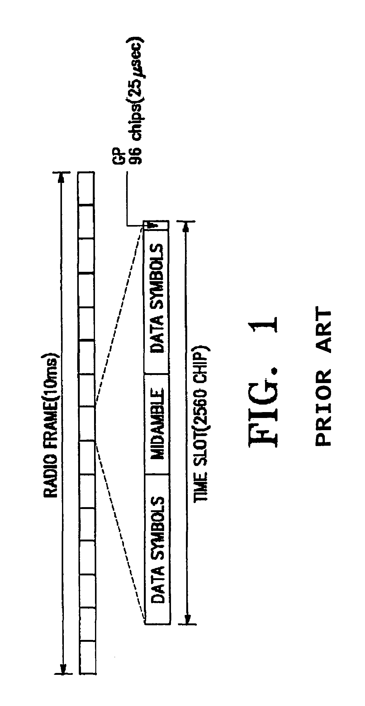
Disclosed a transmission apparatus in a CDMA mobile communication system. Transmission frames each have a plurality of time slots, and each of the time slots includes two data parts having the same length, a midamble intervening between the data parts, and a guard period for dividing the consecutive time slots. The transmission apparatus modulates the frames into a radio signal with a modulation signal and transmits the modulated radio signal using a plurality of antennas. A power amplifier amplifies the radio signal. A controller generates a switching control signal in a guard period of time slots of a frame associated with the radio signal amplified by the power amplifier. A switch switches the amplified radio signal from the power amplifier between a first and a second antenna in response to the switching control signal.

Description

PRIORITY[0001]This application is a Divisional application of U.S. application Ser. No. 09 / 972,814, filed Oct. 5, 2001 which claims priority to an application entitled “TSTD Apparatus and Method for a TDD CDMA Mobile Communication System” filed in the Korean Industrial Property Office on Oct. 5, 2000 and assigned Ser. No. 2000-59389, and an application entitled “TSTD Apparatus and Method for a TDD CDMA Mobile Communication System” filed in the Korean Industrial Property Office on Nov. 9, 2000 and assigned Ser. No. 2000-67558, the contents of both of which are incorporated herein by reference.BACKGROUND OF THE INVENTION[0002]1. Field of the Invention[0003]The present invention relates generally to a transmission / reception apparatus and method for a TDD (Time Division Duplexing) CDMA (Code Division Multiple Access) mobile communication system, and in particular, to a transmission / reception apparatus and method for transmitting frames in a transmit diversity mode to conquer a time-vary...

Claims


Application Information

Patent Timeline
Patent Type & Authority Patents(United States)
IPC IPC(8): H04B7/216G01N1/40H04B1/44H04B1/54H04B1/56H04B7/005H04B7/06H04J3/00H04J13/00H04L5/02H04W52/14H04W52/22H04W52/42
CPCH04B1/44H04B7/0604H04B7/061H04W52/42H04B7/0619H04W52/143H04W52/228H04B1/54H04B7/0673H04B7/0617H04J13/00H04B1/56
Inventor LEE, HYUN-WOOKWAK, BYUNG-JAEKIM, SUNG-JINLEE, JU-HOLEE, YONG-SUKLEE, JONG-HYEUK
Owner SAMSUNG ELECTRONICS CO LTD
Learn More