Switching power supply

Inactive Publication Date: 2010-05-20
PANASONIC CORP
View PDF24 Cites 9 Cited by
  • Summary
  • Abstract
  • Description
  • Claims
  • Application Information

AI Technical Summary

Benefits of technology

[0023]As has been discussed, according to the present invention, even when the first DC voltage fluctuates which is the primary-side input voltage of the switching power supply, an overload on the secondary side is detected according to the secondary current on-period not depending upon the input voltage, thereby achieving stable overload protection.
[0024]Furthermore, the secondary curren

Problems solved by technology

The sensing IC on the secondary side and the photocoupler for outputting the overload signal are, however, expensive power supply components which have increased the costs of switching power supplies and interfered with the size reduction of the switching power supplies.
This technique is not so versa

Method used


Image

  • Switching power supply
  • Switching power supply
  • Switching power supply

Examples


Example

First Embodiment

[0037]The following will describe a switching power supply according to a first embodiment of the present invention.

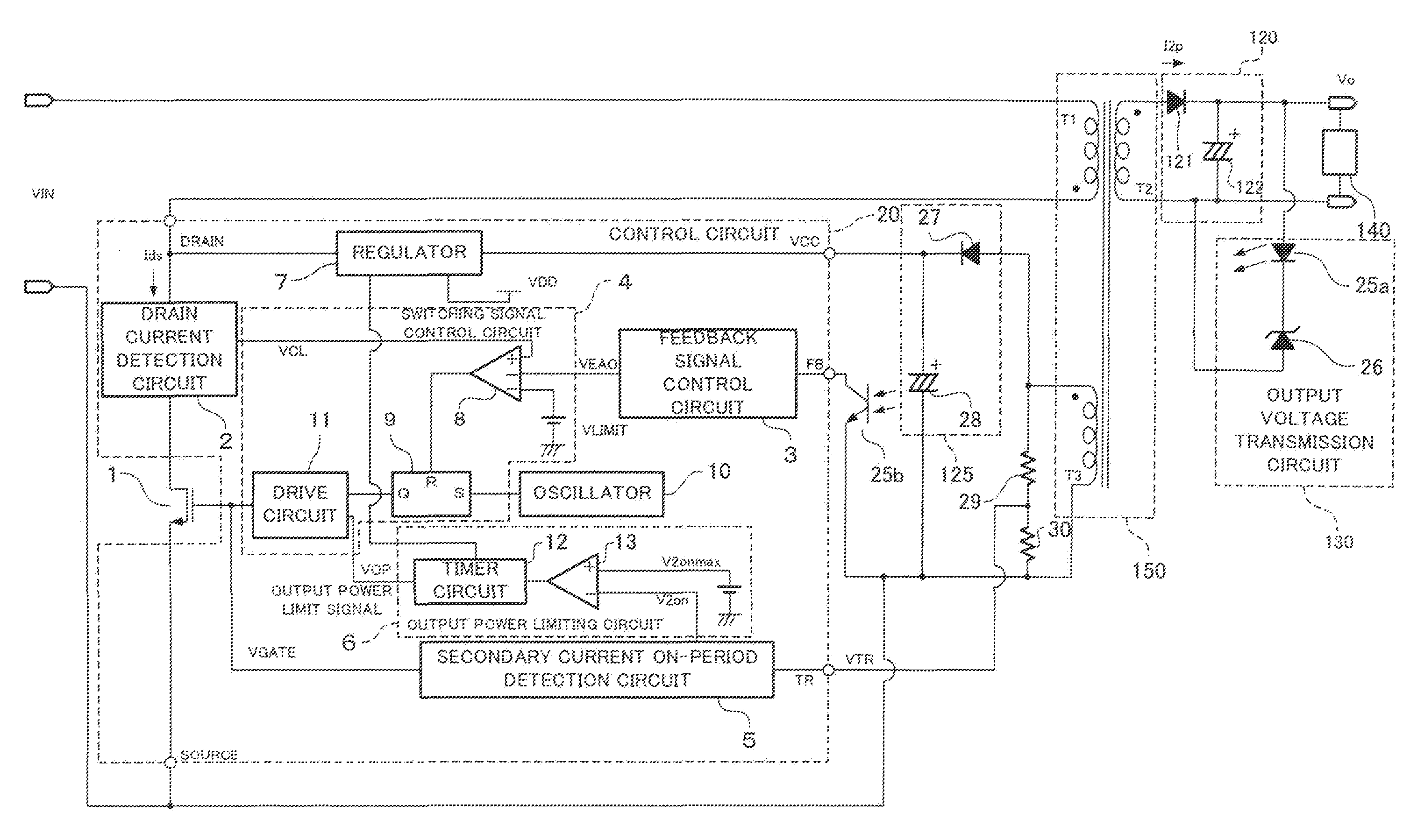
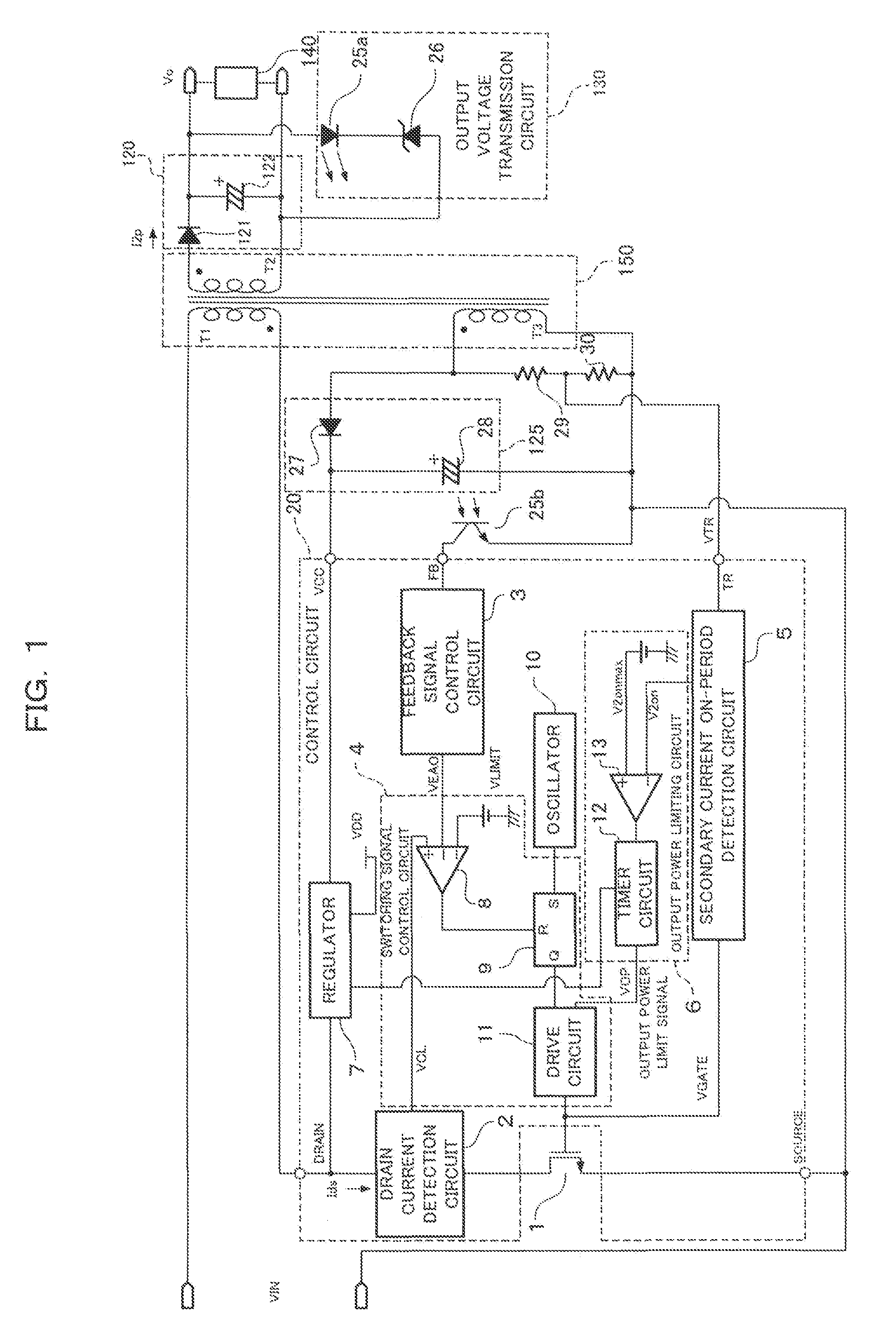
[0038]FIG. 1 is a circuit block diagram showing the configuration of the switching power supply according to the first embodiment. As shown in FIG. 1, a power converter transformer 150 has a primary winding T1, a secondary winding T2, and an auxiliary winding T3. The secondary winding T2 is opposite in polarity from the primary winding T1 and the switching power supply is a flyback power supply.

[0039]The primary winding T1 of the power converter transformer 150 has one terminal connected to the positive terminal of the input side (primary side) of the switching power supply, and the other terminal connected to the negative terminal of the input side (primary side) of the switching power supply via a switching element 1 which is a semiconductor element having a high withstand voltage.

[0040]The switching element 1 has an input terminal, an output terminal...

Example

Second Embodiment

[0104]The following will describe a switching power supply according to a second embodiment of the present invention.

[0105]FIG. 6 is a block diagram showing a structural example of the switching power supply according to the second embodiment. Members corresponding to the members of the first embodiment are indicated by the same reference numerals and the explanation thereof is omitted.

[0106]A control circuit 20 of the switching power supply includes an external terminal OL and a maximum secondary current on-period adjusting circuit 15. The maximum secondary current on-period adjusting circuit 15 has the external terminal OL as an input and supplies a maximum secondary current on-period signal V2onmax to a secondary current on-period comparator 13.

[0107]The maximum secondary current on-period adjusting circuit 15 controls the maximum secondary current on-period signal V2onmax according to the current or voltage of the OL terminal.

[0108]In this configuration, for exa...

Example

Third Embodiment

[0110]The following will describe a switching power supply according to a third embodiment of the present invention.

[0111]FIG. 7 is a block diagram showing a structural example of the switching power supply according to the third embodiment. Members corresponding to the members of the first embodiment are indicated by the same reference numerals and the explanation thereof is omitted.

[0112]In the switching power supply, a control circuit 20 includes a maximum secondary current on-period adjusting circuit 15 and a continuity / discontinuity determining circuit 16. The maximum secondary current on-period adjusting circuit 15 is connected to the continuity / discontinuity determining circuit 16, and the continuity / discontinuity determining circuit 16 is connected to a secondary current on-period detection circuit 5.

[0113]The continuity / discontinuity determining circuit 16 determines whether the switching power supply is in continuous mode or discontinuous mode based on an o...


PUM


Abstract

According to the present invention, when a secondary current on period T2on reaches a predetermined maximum secondary current on-period, an overload is detected and an output power is controlled to decrease. Further, a maximum secondary current on-period signal is set so as to correspond to a secondary current on-period when constant voltage control is performed on an output voltage.

Description

REFERENCE TO RELATED APPLICATIONS[0001]The disclosure of Japanese Patent Application No. 2008-295004 filed Nov. 19, 2008 including specification, drawings and claims is incorporated herein by reference in its entirety.FIELD OF THE INVENTION[0002]The present invention relates to a switching power supply which acts as a power supply and has an overload protection function for a secondary side output against the load of the power supply.BACKGROUND OF THE INVENTION[0003]In recent years, in switching power supplies used as power supplies for electronic equipment and so on, an overload protection function has become necessary for secondary side outputs against the loads of the power supplies.[0004]In a known overload protection technique for a secondary side output, a current to a load is monitored using a sensing resistor and the like on the secondary side, an overload is detected using a sensing IC and the like on the secondary side, and then an overload signal is directly fed back to t...

Claims


Application Information

Patent Timeline
IPC IPC(8): H02M3/335
CPCH02M3/33507H02M1/32
Inventor MOROTA, NAOHIKOMURATA, KAZUHIRO
Owner PANASONIC CORP
Why Eureka
Try Eureka