Method and system for improved solid area and heavy shadow uniformity in printed documents

a technology of solid area and heavy shadow, applied in the field of minimizing cross-process non-uniformities in solid and heavy shadow regions of printed documents, can solve the problems of large image quality defects, difficult control, undesirable visible color shift of overlaid colors, etc., and achieve the effect of minimizing cross-process non-uniformities

Inactive Publication Date: 2010-08-26
XEROX CORP
View PDF14 Cites 7 Cited by
  • Summary
  • Abstract
  • Description
  • Claims
  • Application Information

AI Technical Summary

Benefits of technology

[0021]According to one aspect of the present disclosure, a method for minimizing cross-process non-uniformities in solid and heavy shadow regions of printed documents is provided. The method includes marking with a marking engine an image on an image bearing surface moving in a process direction; generating profile data of the image by sensing an optical characteristic of...

Problems solved by technology

Streaks are a major image quality defect for both image-on-image (IOI) and Intermediate Belt Transfer (IBT) Tandem xerography.
In a color xerographic machine, streaks in single color separations that may be unobjectionable alone can cause an undesirable visible color shift for overlaid colors.
Image printing technologies may contain several sources of streaks, which can sometimes be difficult to control via image printing system design or image printing system optimization.
Streaks may be caused by “non-ideal” responses of xerographic components in the marking engine of the image printing system.
The source of these artifacts may be found in contamination of the development wires, photoreceptor (P/R) non-uniformities, fuser non-uniformities, charge device contamination, etc.
Streaks may also be caused by non-uniformity of the raster output scanning device spot-size or intensity variations.
Non-uniformities in the cross-process direction (e.g., streaks) in halftones and solid regions may be very problematic to mitigate using spatial exposure modifications since many Raster Output Scanner (ROS) devices only support modulations in the cross-process direction at low spatial frequency.
In other words, the ROS devices do not have the capability to adjust intensity fast enough to compensate at medium to high frequency (i.e., very low frequency intensity adjustment is achievable).
This makes compensating higher spatial frequency non-uniformities in the cross-process direction, such as charge device non-uniformities, extremely difficult, using the exposure intensity actuator.
Also, many ROS devices also do not support adjusting intensity on a pixel-by-pixel basis in the cross-process (i.e., fast-scan) direction.
This makes compensating for higher spatial frequency cross-process non-uniformity through spatial exposure modulation using such devices nearly impossible.
However, the streak correction system described in the above mentioned references cannot correct streaks occurring in solid regions (i.e. be...

Method used


Image

  • Method and system for improved solid area and heavy shadow uniformity in printed documents
  • Method and system for improved solid area and heavy shadow uniformity in printed documents
  • Method and system for improved solid area and heavy shadow uniformity in printed documents

Examples


Embodiment Construction

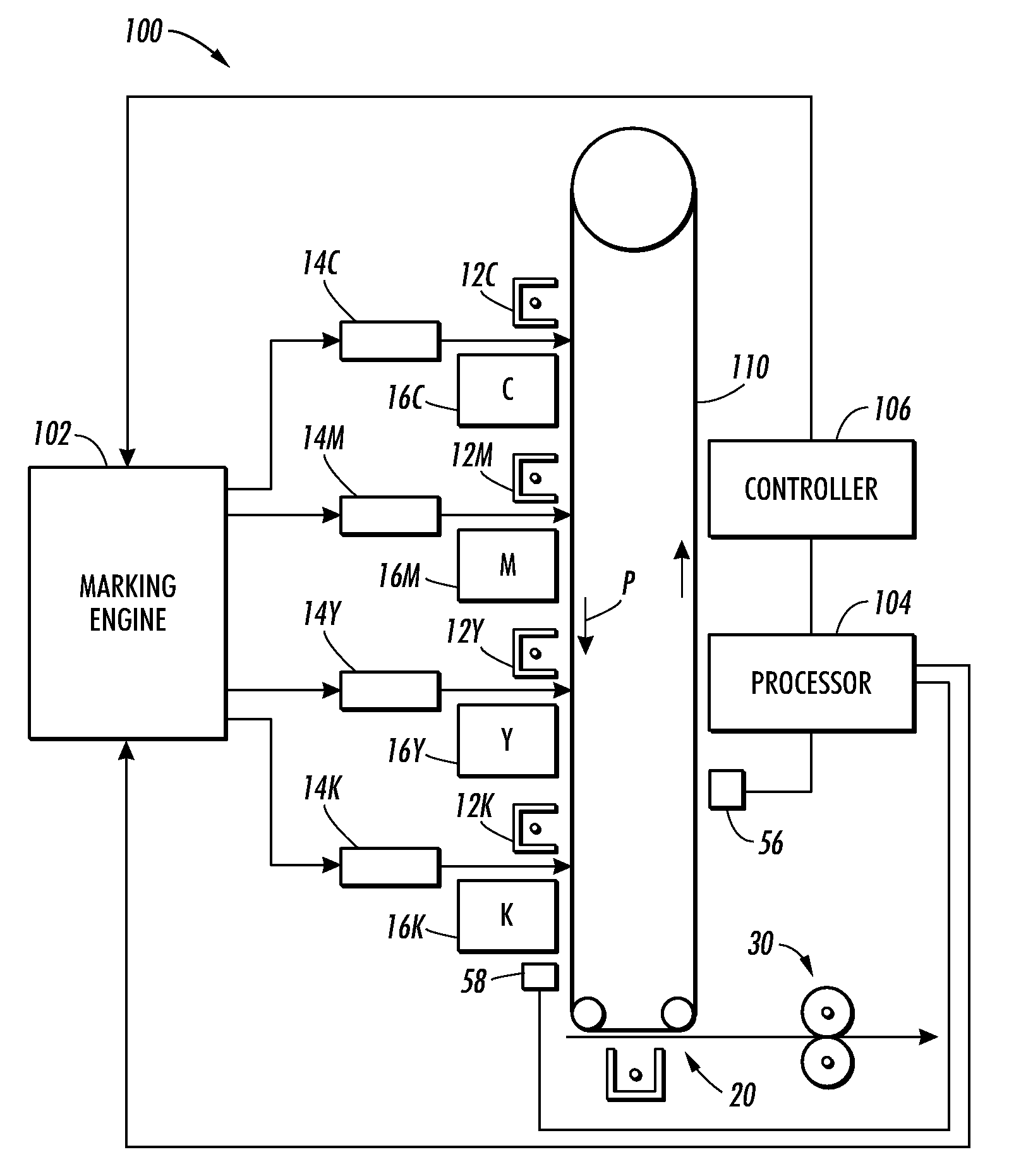
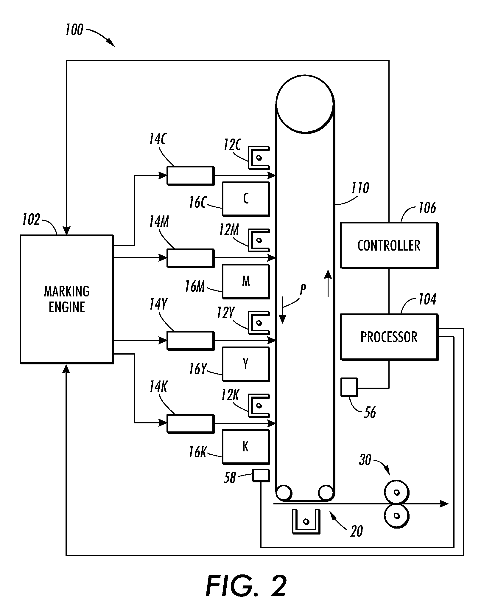
[0039]The present disclosure addresses an issue in the area of uniformity correction, namely, the cross-process uniformities (i.e., streaks) in solids / shadow regions. The present disclosure proposes the use of a higher spatial frequency actuator (i.e., the image based control) in combination with the lower spatial frequency actuators (i.e., the xerographic actuators) to solve this issue (e.g., to improve cross-process uniformities (i.e., streaks) in solid regions including the shadow regions).

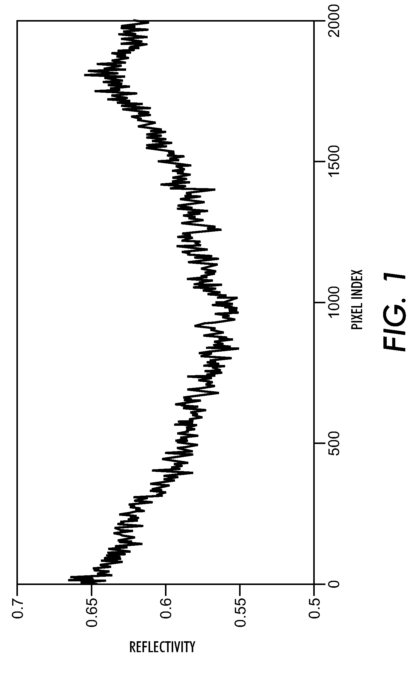
[0040]The present disclosure proposes a two-step solution. In the first step, the darkest cross-process area of the solid test patch or image is calculated from the uniformity profile, and the xerographic actuators are adjusted until the entire image is shifted so that the lightest cross-process area in the solid region becomes the darkest level measured in the original uniformity profile. In the second step, the contone (i.e., continuous tone) values of the digital image are adjusted on a pi...


PUM


Abstract

A method for minimizing cross-process non-uniformities in solid and heavy shadow regions of printed documents is provided. The method includes marking with a marking engine an image on an image bearing surface moving in a process direction; generating profile data of the image by sensing an optical characteristic of the image in a cross-process direction; adjusting at least one control actuator of the marking engine so as to shift the characteristic of a subsequent marked image in the cross-process direction to at least a target value; and generating a spatially varying tone reproduction curve to smooth the characteristic of the subsequent marked image towards the target value.

Description

BACKGROUND[0001]1. Field[0002]The present disclosure relates to a method and a system for minimizing cross-process non-uniformities in solid and heavy shadow regions of printed documents.[0003]2. Description of Related Art[0004]An electrophotographic, or xerographic, image printing system employs an image bearing surface, which is charged to a substantially uniform potential so as to sensitize the surface thereof. The charged portion of the image bearing surface is exposed to a light image of an original document being reproduced. Exposure of the charged image bearing surface selectively dissipates the charge thereon in the irradiated areas to record an electrostatic latent image on the image bearing surface corresponding to the image contained within the original document. The location of the electrical charge forming the latent image is usually optically controlled. More specifically, in a digital xerographic system, the formation of the latent image is controlled by a raster outp...

Claims


Application Information

Patent Timeline
IPC IPC(8): G06F15/00
CPCG03G15/5041G03G2215/00042
Inventor BURRY, AARON M.PAUL, PETERZONA, MICHAEL F.
Owner XEROX CORP
Why Eureka
Try Eureka