Microscope having internal focusing

Active Publication Date: 2010-08-26
CARL ZEISS MICROSCOPY GMBH
View PDF5 Cites 8 Cited by
  • Summary
  • Abstract
  • Description
  • Claims
  • Application Information

AI Technical Summary

Benefits of technology

[0009]Therefore, it is the object of the invention to provide a laser scanning microscope and a method for controlling the latter which also makes possible a sharp imaging of a sample with standard objectives without relative movement of the microscope objective and sample.
[0015]In a preferred embodiment, the laser scanning microscope is outfitted with a control unit which repeatedly scans an optical section of a sample by means of the scanner, and a different focus position can be adjusted subsequently by displacing the tube lens. In this way, a stack of optical sections from different focus distances can advantageously be recorded in a z-scan without relative movement between the microscope objective and sample. In a z-scan of this kind, the control unit preferably determines a plurality of discrete focus positions step by step over a depth range of the sample and, in each focus position, scans a respective optical section as part of a z-stack recording. In this way, a z-stack can be recorded in an automated manner.
[0016]Surprisingly, it was found that a laser scanning microscope with an aperture between 0.45 and 0.53, in particular an aperture of 0.45 or 0.53, and / or with an immersion medium having a refractive index between 1.31 and 1.36 can adjust the focus position in a large depth range of 200 μm.

Problems solved by technology

However, the relative movements between the objective and the sample are problematic under some circumstances.
However, the required special objective is extremely costly.

Method used


Image

  • Microscope having internal focusing
  • Microscope having internal focusing
  • Microscope having internal focusing

Examples


Embodiment Construction

[0026]It is to be understood that the figures and descriptions of the present invention have been simplified to illustrate elements that are relevant for a clear understanding of the present invention, while eliminating, for purposes of clarity, many other elements which are conventional in this art. Those of ordinary skill in the art will recognize that other elements are desirable for implementing the present invention. However, because such elements are well known in the art, and because they do not facilitate a better understanding of the present invention, a discussion of such elements is not provided herein.

[0027]The present invention will now be described in detail on the basis of exemplary embodiments.

[0028]Corresponding parts have identical reference numbers in all of the drawings.

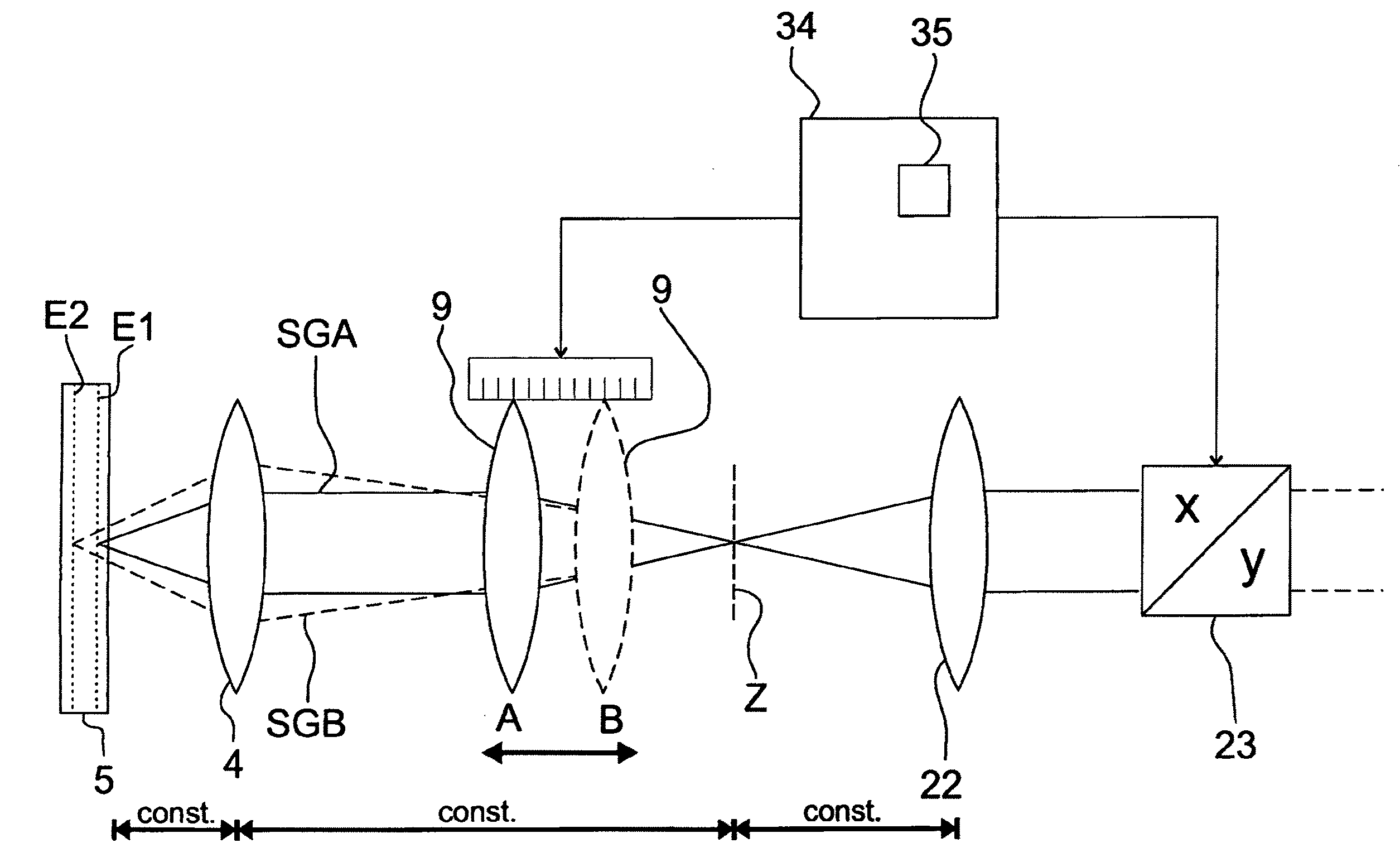
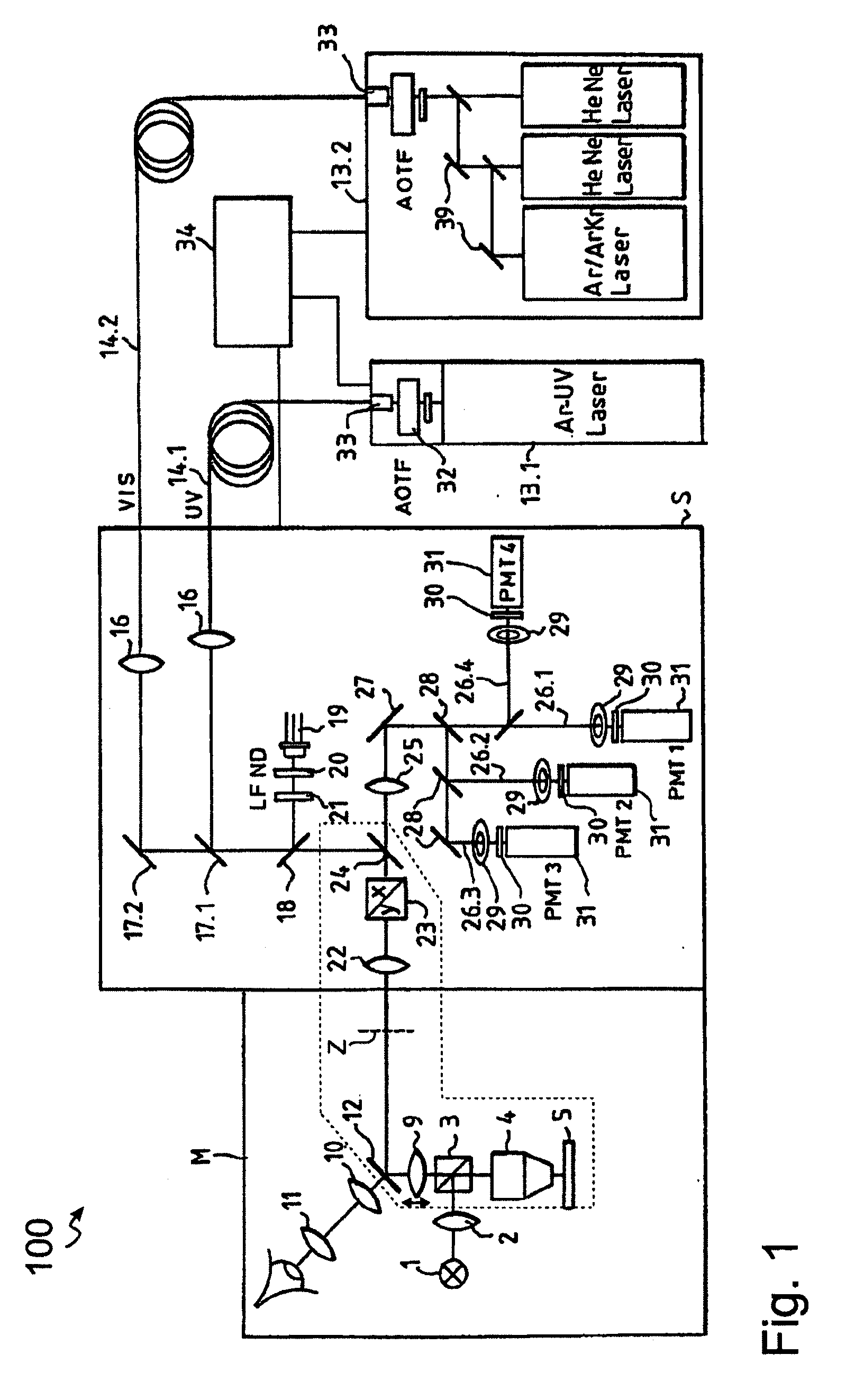
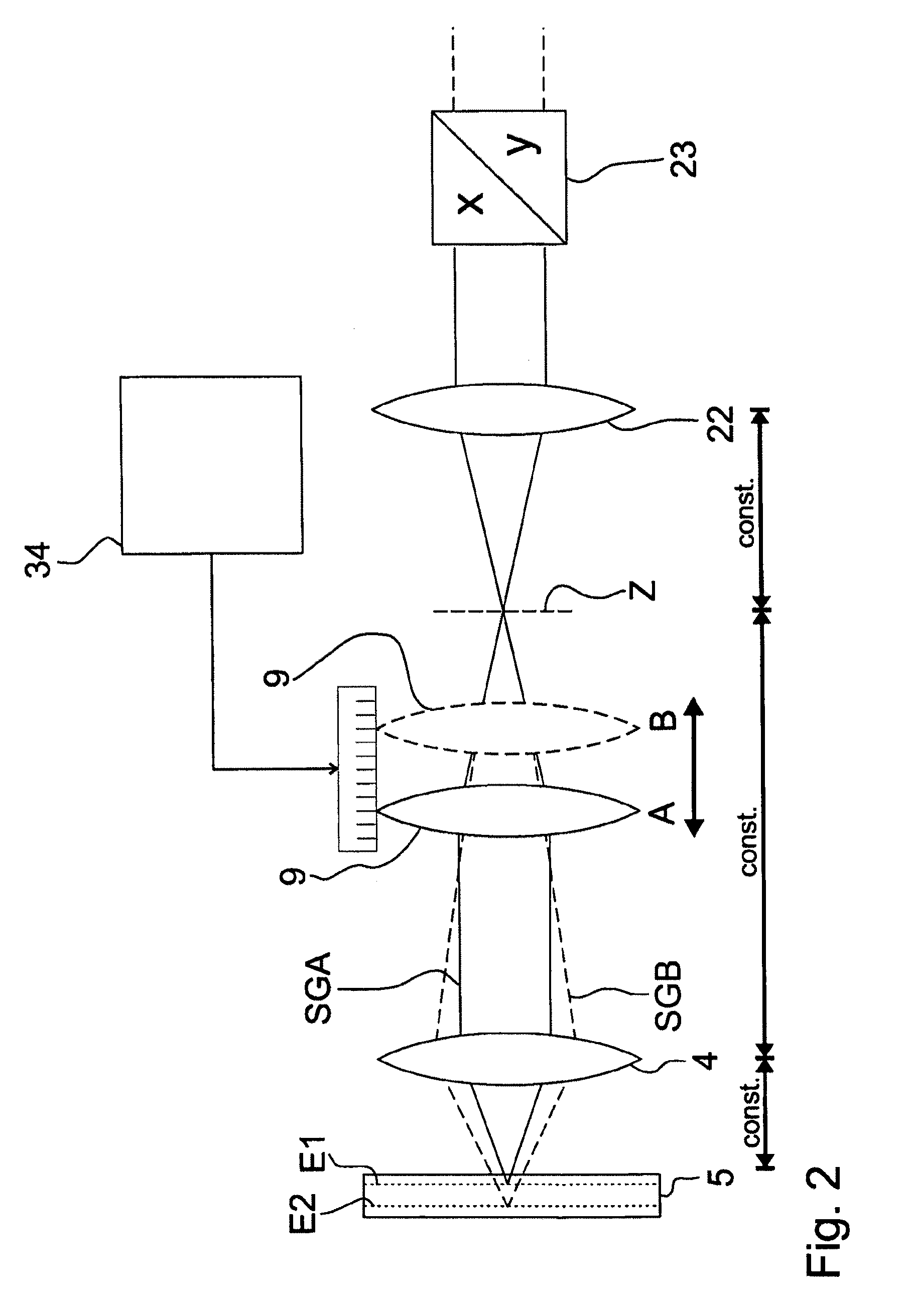
[0029]FIG. 1 shows a microscope 100 schematically. It comprises a microscope unit M and a scan head S which share a common optical interface by means of an intermediate imaging in an intermediate ...


PUM


Abstract

The invention relates to a laser scanning microscope with a scanner and a microscope objective, and to a control method for such a microscope. In order to obtain sharp imaging of the sample in a laser scanning microscope, the distance between the microscope objective and the sample is usually varied for adjusting the focus position. However, relative movements between the objective and the sample can be problematic. In view of the costly special objective, internal focusing of the objective is a disadvantageous solution. An improved laser scanning microscope should make it possible to sharply image a sample with standard objectives without relative movement between the microscope objective and sample. According to the invention, a tube lens is provided which is displaceable along the optical axis, and the focus position is adjustable relative to a front optical element of the microscope objective by adjusting the tube lens.

Description

[0001]The present application claims priority from PCT Patent Application No. PCT / EP2008 / 006457 filed on Aug. 6, 2008, which claims priority from German Patent Application No. 10 2007 038 579.1 filed on Aug. 16, 2007, the disclosure of which is incorporated herein by reference in its entirety.BACKGROUND OF THE INVENTION[0002]1. Field of the Invention[0003]The invention is directed to a laser scanning microscope and to a control method for a laser scanning microscope of this kind.[0004]2. Description of Related Art[0005]In order to obtain sharp imaging of the sample in a laser scanning microscope, the distance between the microscope objective and the sample is usually varied to adjust the focus position. To this end, either the sample stage with the sample or the microscope objective can be moved. It is also possible to combine the two movements.[0006]However, the relative movements between the objective and the sample are problematic under some circumstances. For example, in electro...

Claims


Application Information

Patent Timeline
IPC IPC(8): G02B21/02
CPCG02B21/0048G02B21/241G02B21/0072G02B21/006
Inventor PACHOLIK, JOERGHANFT, MARCOHUHSE, DIETER
Owner CARL ZEISS MICROSCOPY GMBH
Why Eureka
Try Eureka