Centrifugal compressor

a centrifugal compressor and compressor technology, applied in the direction of machines/engines, manufacturing tools, liquid fuel engines, etc., can solve the problems of difficult reproducible manufacturing of centrifugal compressors, no clearance ideally between the shroud and the vanes of the diffuser, etc., to prevent any pressure loss

Active Publication Date: 2010-08-26
DYSON TECH LTD
View PDF3 Cites 35 Cited by
  • Summary
  • Abstract
  • Description
  • Claims
  • Application Information

AI Technical Summary

Benefits of technology

[0021]Preferably, the method includes mounting the impeller to a shaft and rotatably mounting the shaft to the diffuser. Consequently, the impeller may be accurately aligned relative to the diffuser.
[0022]The diffuser advantageously comprises a hub, a perimeter wall, and a plurality of axial vanes that extend between the hub and the perimeter wall, and the method comprises securing the shroud to the perimeter wall. The shroud and diffuser then cooperate to direct the flow of fluid through the compressor from a radial direction to an axial direction. Preferably, the shroud is adhered to the perimeter wall. Consequently, following separation of the shroud from the impeller and diffuser, the shroud can be conveniently secured to the diffuser such that the clearance between the shroud and impeller is maintained. Additionally, an effective seal is created between the shroud and diffuser thereby preventing any pressure losses that might otherwise arise due to leakage.

Problems solved by technology

Additionally, no clearance ideally exists between the shroud and the vanes of the diffuser, since any clearance presents a pathway for the working fluid to flow over the vanes without being turned.
Owing to manufacturing tolerances, it is generally difficult to reproducibly manufacture a centrifugal compressor having a small, well-defined clearance between the shroud and impeller while simultaneously ensuring that there is no clearance between the shroud and the diffuser vanes.

Method used


Image

  • Centrifugal compressor
  • Centrifugal compressor
  • Centrifugal compressor

Examples


Embodiment Construction

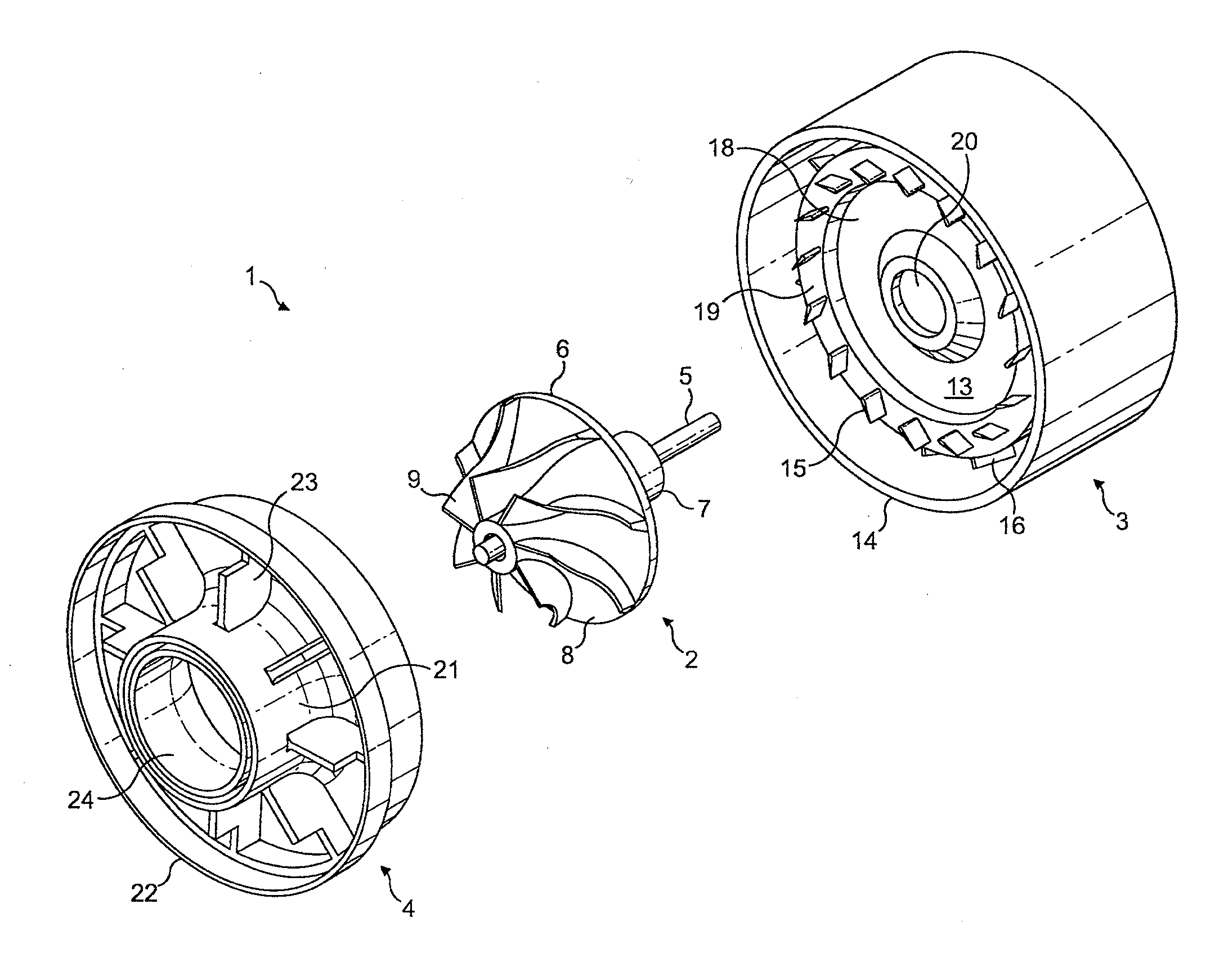
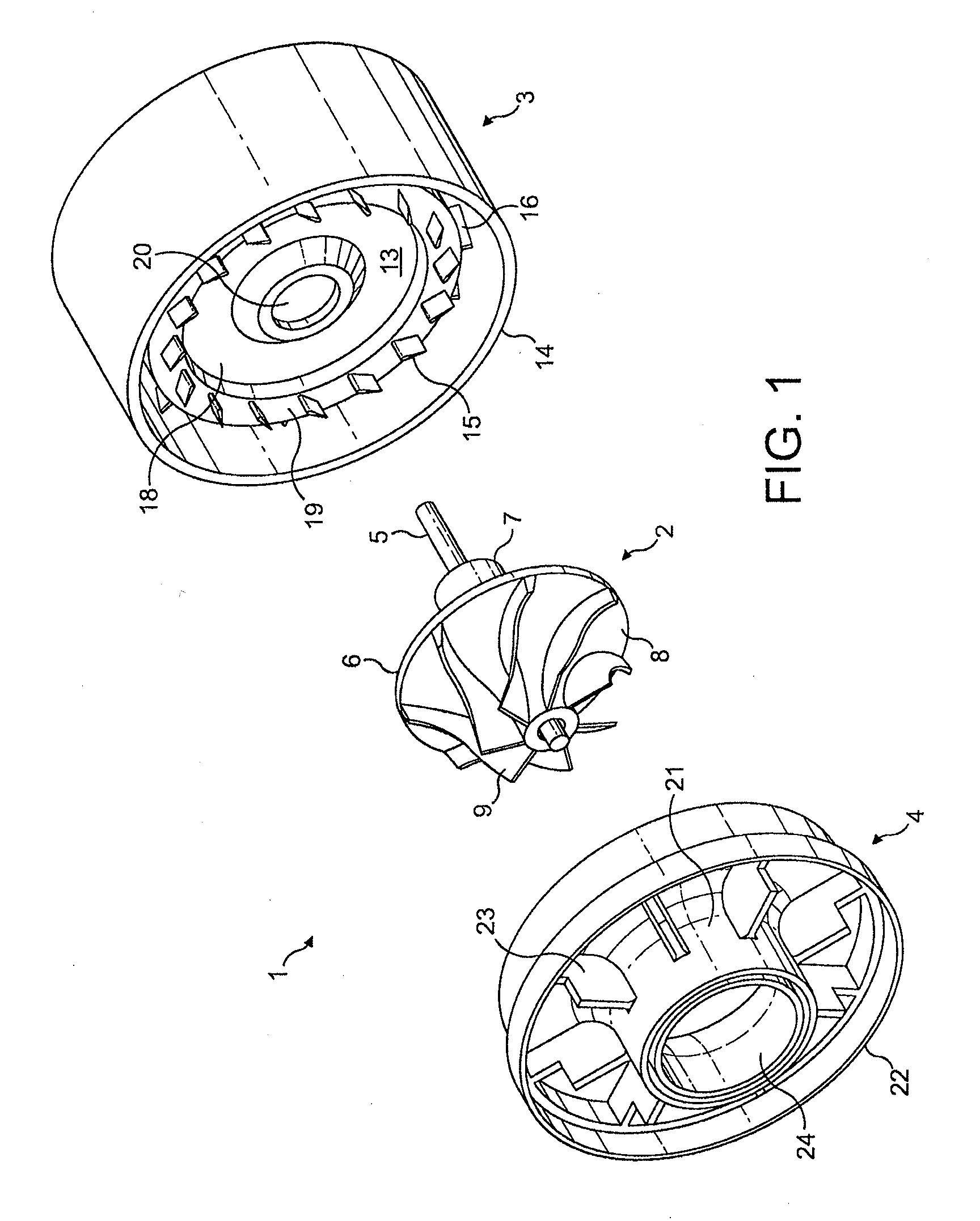
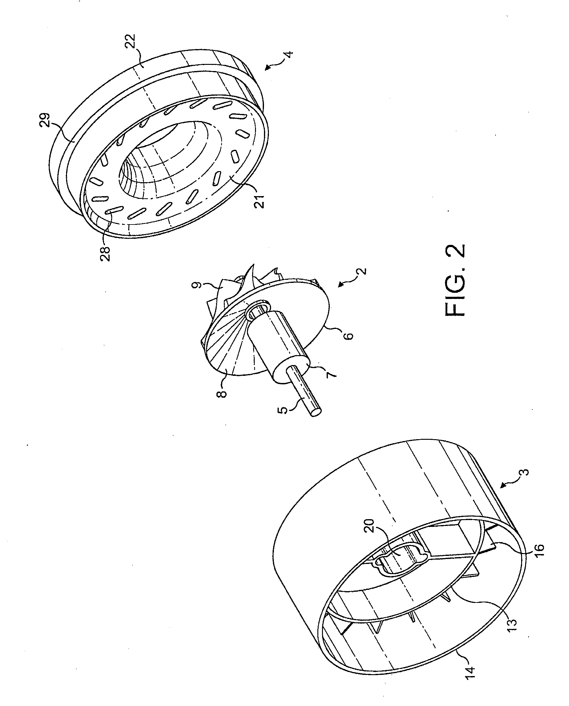
[0030]The centrifugal compressor 1 of FIGS. 1 to 3 comprises a rotor 2, a diffuser 3, and a shroud 4.

[0031]The rotor 2 comprises a shaft 5 to which are mounted an impeller 6 and a bearing cartridge 7. The impeller 6 is a semi-open impeller comprising a hub 8 around which a plurality of blades 9 are supported. The bearing cartridge 7 comprises a pair of spaced bearings 10, preloaded by a spring 11, and surrounded by a sleeve 12.

[0032]The diffuser 3 comprises a hub 13, a perimeter wall 14, a plurality of radial vanes 15, and a plurality of axial vanes 16. A step 17 is formed in the upper surface of the hub 13 so as to define a central portion 18 and an outer annulus 19. The radial vanes 15 are two-dimensional aerofoils spaced circumferentially around the outer annulus 19. The perimeter wall 14 is spaced from and encircles the hub 13. The axial vanes 16 are two-dimensional aerofoils that extend between and secure the perimeter wall 14 to the hub 13.

[0033]The rotor 2 is rotatably mounte...


PUM

PropertyMeasurementUnit
depthaaaaaaaaaa
perimeteraaaaaaaaaa
pressureaaaaaaaaaa

Abstract

A centrifugal compressor that includes an impeller, a diffuser and a shroud. One of the diffuser and shroud includes a plurality of recesses and the other of the diffuser and shroud includes a plurality of radial vanes. The shroud covers the impeller and diffuser such that each radial vane projects into a respective recess.

Description

REFERENCE TO RELATED APPLICATIONS[0001]This application claims the priority of United Kingdom Application No. 0903050.3, filed Feb. 24, 2009, the entire contents of which are incorporated herein by reference.FIELD OF THE INVENTION[0002]The present invention relates to a centrifugal compressor.BACKGROUND OF THE INVENTION[0003]A known design of centrifugal compressor comprises an impeller and vaned diffuser covered by a static shroud. In order to maximise performance, the clearance between the impeller and the shroud is ideally as small as possible while allowing for minor changes in the impeller and shroud that arise during subsequent use of the compressor. Additionally, no clearance ideally exists between the shroud and the vanes of the diffuser, since any clearance presents a pathway for the working fluid to flow over the vanes without being turned. Owing to manufacturing tolerances, it is generally difficult to reproducibly manufacture a centrifugal compressor having a small, well...

Claims


Application Information

Patent Timeline
Patent Type & Authority Applications(United States)
IPC IPC(8): F04D29/44B23P11/00
CPCF04D29/624F05D2250/52F05D2300/43F04D29/4226Y10T29/49243F04D29/444F04D17/08F04D29/44
Inventor CHILDE, MATTHEW JOHNCROSSLEY, PETER LEE
Owner DYSON TECH LTD
Why Eureka
Try Eureka