

Rolling Ball Type Two-Stage Low Speed Changer Device
- Summary
- Abstract
- Description
- Claims
- Application Information
AI Technical Summary
Benefits of technology
Problems solved by technology
Method used
Image

Examples
first embodiment
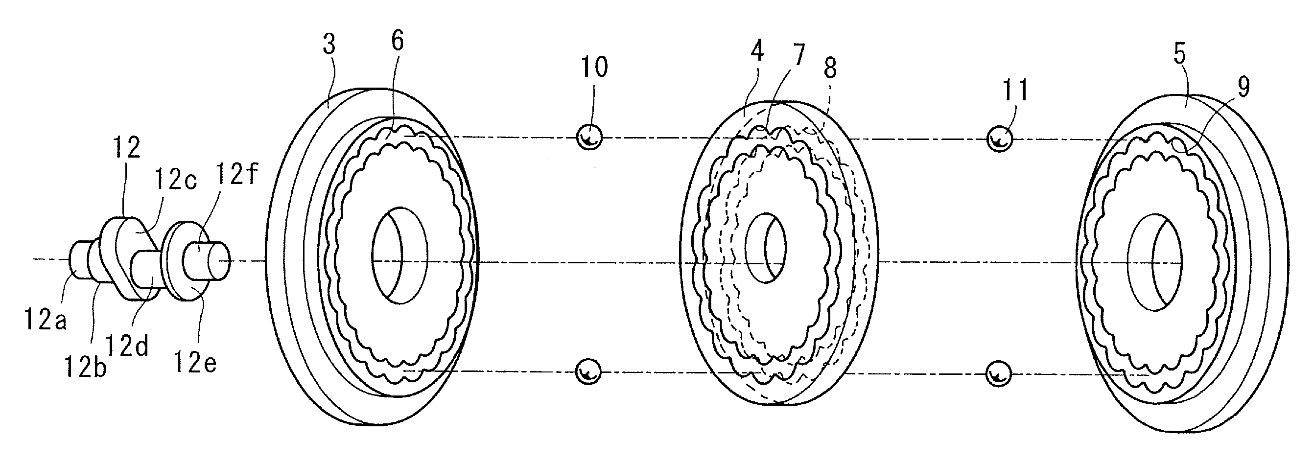
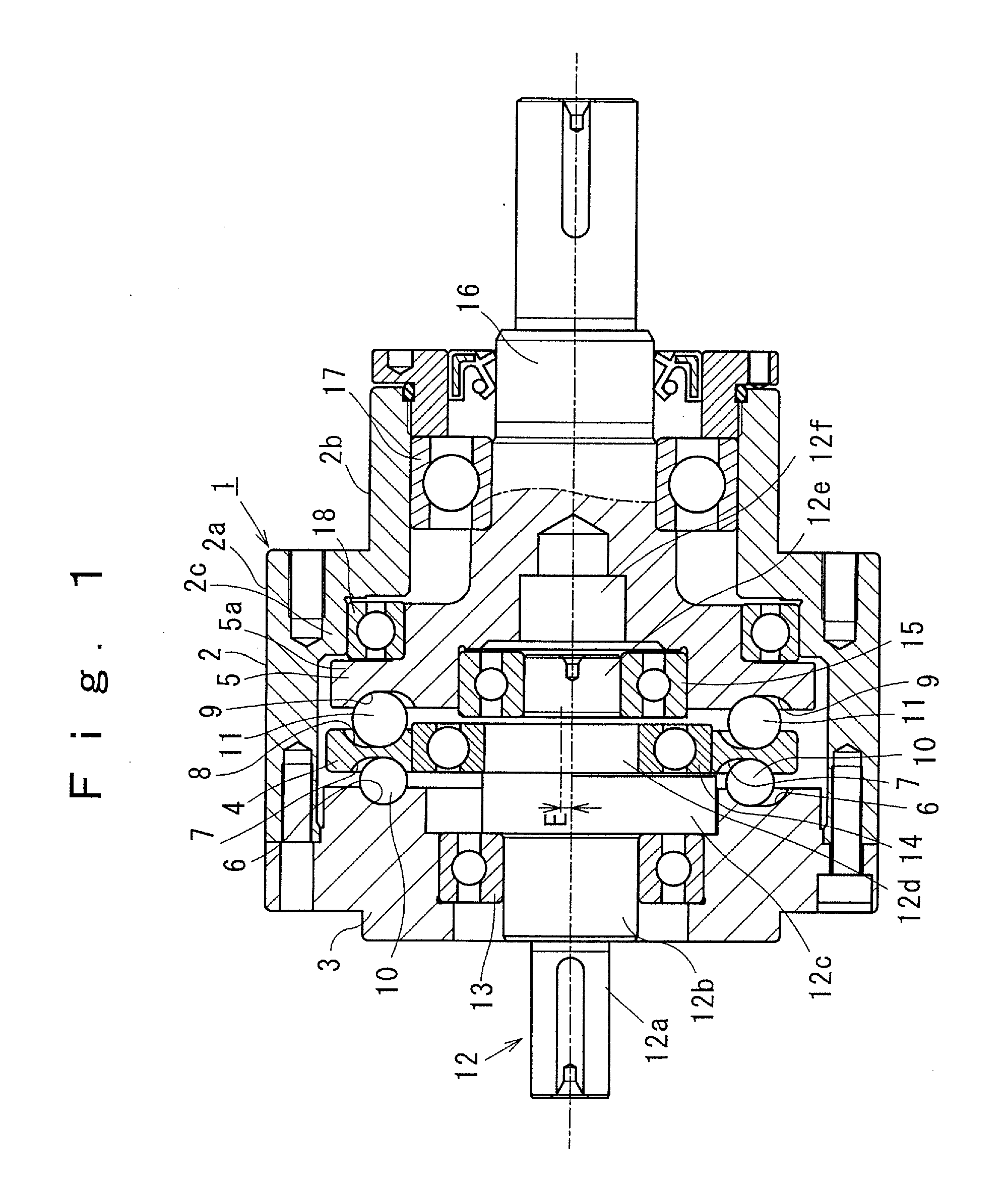
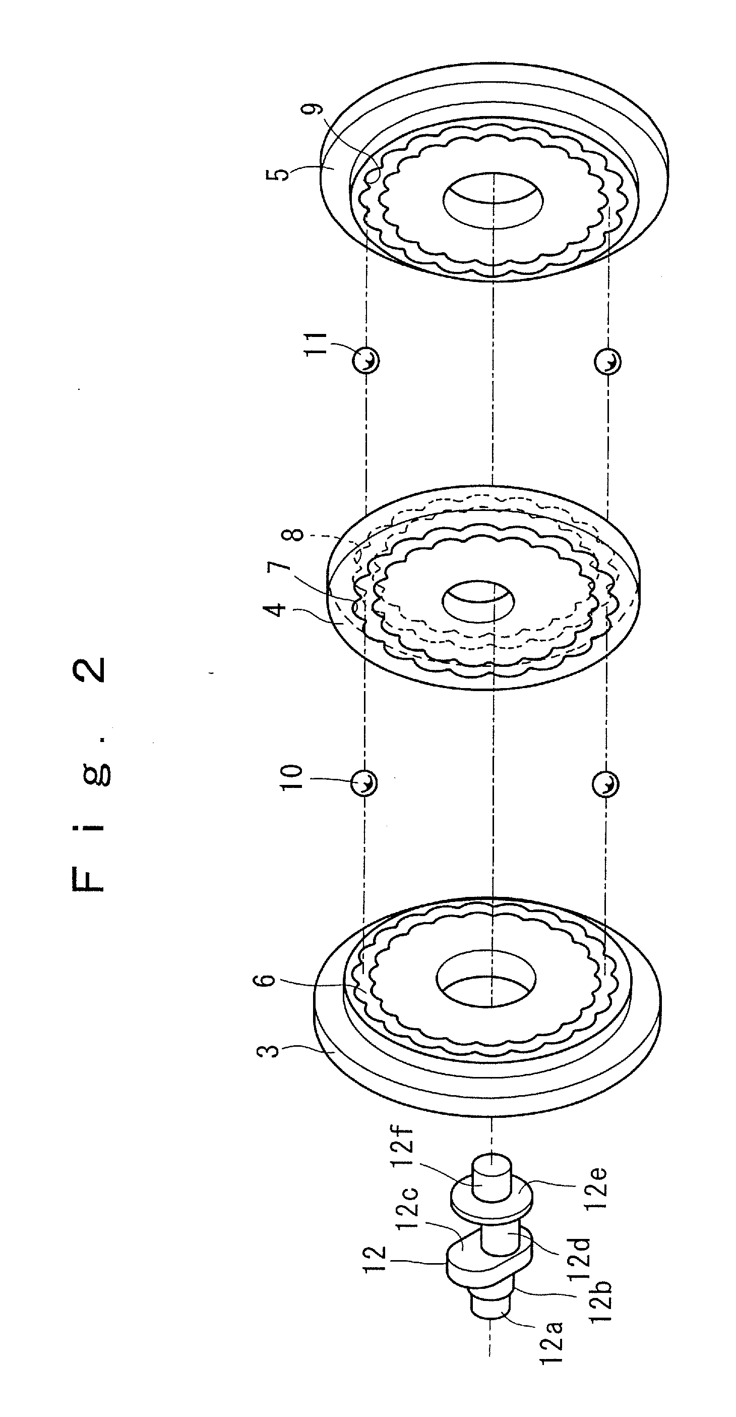
[0062]Referring to FIGS. 1 through 4 which show a rolling ball type two-stage low speed changer device 1 according to the invention, a cylindrical housing 2 has a diameter increased portion 2a and a diameter reduced portion 2b in the rolling ball type two-stage low speed changer device 1. Within the diameter-increased portion 2a, a stationary disc 3, an eccentric disc 4 and an output disc 5 are placed to be space opposed in parallel with each other.
[0063]A hypo-based groove 6 is provided with one side surface of the stationary disc 3, and an epi-based groove 7 is formed on one side surface of the eccentric disc 4 in registry with the hypo-based groove 6. On the other side surface of the eccentric disc 4, a hypo-based groove 8 is defined. In registry with the hypo-based groove 8, an epi-based groove 9 is provided with one side surface of the output disc 5.
[0064]Between the stationary disc 3 and the eccentric disc 4, a plurality of first rollable balls 10 are provided, each of which p...
second embodiment
[0096]FIG. 5 shows the invention in which the hypo-based groove 6 (8) and the epi-based groove 7 (9) are alternately exchanged among the stationary disc 3, the eccentric disc 4 and the output disc 5.
[0097]Namely, the stationary disc 3 has an epi based groove 20 circumferentially defined along the epicycloidal curve with peripheral teeth as the first number of lobes z1. The eccentric disc 4 has a hypo-based groove 21 circumferentially defined along the hypocycloidal curve with peripheral teeth as the second number of lobes z2, and having an epi-based groove 22 circumferentially defined along the epicycloidal curve with peripheral teeth as the third number of lobes z3.
[0098]The output disc 5 has a hypo-based groove 23 circumferentially defined along the hypocycloidal curve with peripheral teeth as the fourth number of lobes z4.
[0099]Following empirical formulas A1, B1 and C1 are achieved among the first number of lobes z1, the second number of lobes z2, the third number of lobes z3 an...
third embodiment
[0101]FIG. 6 shows the invention in which the epi-based groove 7 (9) and the hypo-based groove 6 (8) are arranged to be exchangeable with other ones.
[0102]The stationary disc 3 has a main disc plate 3A and an adjunctive disc plate 3B which carries the hypo-based groove 6. On one side surface of the main disc plate 3A, a circular recess 3a is provided in correspondence to the adjunctive disc plate 3B. A peripheral side surface of the adjunctive disc plate 3B has a male thread 3b, and an inner side wall of the recess 3a has an internal thread 3c in correspondence to the male thread 3b.
[0103]The adjunctive disc plate 3B is detachably mounted on the main disc plate 3A by turning the male thread 3b against the internal thread 3c in one direction and another direction. The male thread 3b is made in such a direction as to tighten against the internal thread 3c when the adjunctive disc plate 3B is subjected to the rotational transmission from the eccentric disc 4 during the speed reducing ...
PUM
 Abstract
Description
Claims
Application Information