
Wiper having tilting multi-blade

a multi-blade, wiper technology, applied in the field of wipers, can solve the problems of easy damage or twisted blades, reduced service life of wipers, so as to prolong the life of wipers, enhance the washing ability of wipers, and minimize breakage

Inactive Publication Date: 2010-09-02
JEONG HYUN CHAN
View PDF6 Cites 6 Cited by
  • Summary
  • Abstract
  • Description
  • Claims
  • Application Information

AI Technical Summary

Benefits of technology

[0007]Accordingly, the present invention has been made keeping in mind the above problems occurring in the prior art, and an object of the present invention is to provide a wiper having a tilting multi-blade in which reciprocating blade tilting operation is conducted by a wiper arm unlike the conventional technique in which the blade tilting operation is conducted by a tilting bridge of the blade, and a blade holder is sectioned into several parts, and the blade has a multiple structure, so that compression force, washing ability and water drainage ability can be enhanced, and even though it is used for a long period, a wave phenomenon does not occur.
[0008]Another object of the present invention is to provide a wiper in which the multi-blade includes independent blade lips so that a contact area between the multi-blade and a windshield is increased, thus enhancing the washing ability of the wiper, and minimizing breakage, degradation, and torsion of the blade, thereby extending the lifetime of the wiper.
[0011]The left water outlets and right water outlets may be alternately formed in the first through fourth blade lips in directions angled to a longitudinal direction of the multi-blade such that the left water outlets and the right water outlets are misaligned from each other, so that the first through fourth blade lips are sectioned into a plurality of parts by the left and right water outlets to consecutively eliminate a wave phenomenon induced by wiping, and impurities or washing water are discharged out of the multi-blade through the left and right water outlets.
[0014]In a wiper having a tilting multi-blade according to the present invention, the multi-blade which is held by a blade holder has independent multiple blade lips, so that a contact area between the blade and a windshield is increased, thus enhancing the washing ability of the wiper, and minimizing breakage, degradation, and torsion of the blade, thereby extending the lifetime of the wiper.
[0015]Furthermore, unlike the conventional technique in which a blade has a single blade lip, the multi-blade may include quintuple or more blade lips as conditions required in a machine, such as a vehicle, to which the wiper is mounted. Therefore, the present invention can reliably eliminate dust, dirt or rain smeared on the windshield when traveling, thereby making the view of a user clear for the sake of safe driving. In addition, even though the wiper is used for a long period of time, a wave phenomenon does not occur, thus preventing an accident attributable to obstruction of the view of the user when driving. Moreover, the durability of the wiper is enhanced, a loss of labor efforts, and economic loss attributable to frequent replacement of the blade can be markedly reduced.

Problems solved by technology

However, to achieve the above purpose, there is a limitation in that the reciprocating tilting bridge 71 must be relatively thin, typically, the thickness thereof must be about 1 mm or less.
Therefore, the blade 72 is easily damaged or twisted.
Furthermore, a degradation phenomenon attributable to changes in weather, solar light, use over a long time, etc. occurs.
Second, in the case of a blade having a single blade lip, because a contact area between the blade and a windshield is relatively small, there is a limitation in the ability to remove impurities, such as dirt or rain.
Therefore, uniform compression force cannot be applied over the entire length of the blade.
Thereby, there is a limitation in the washing ability, and the problems of a loss of labor efforts and economic loss still remains.

Method used


Image

  • Wiper having tilting multi-blade
  • Wiper having tilting multi-blade
  • Wiper having tilting multi-blade

Examples


Embodiment Construction

[0026]Hereinafter, a preferred embodiment of the present invention will be described in detail with reference to the attached drawings.

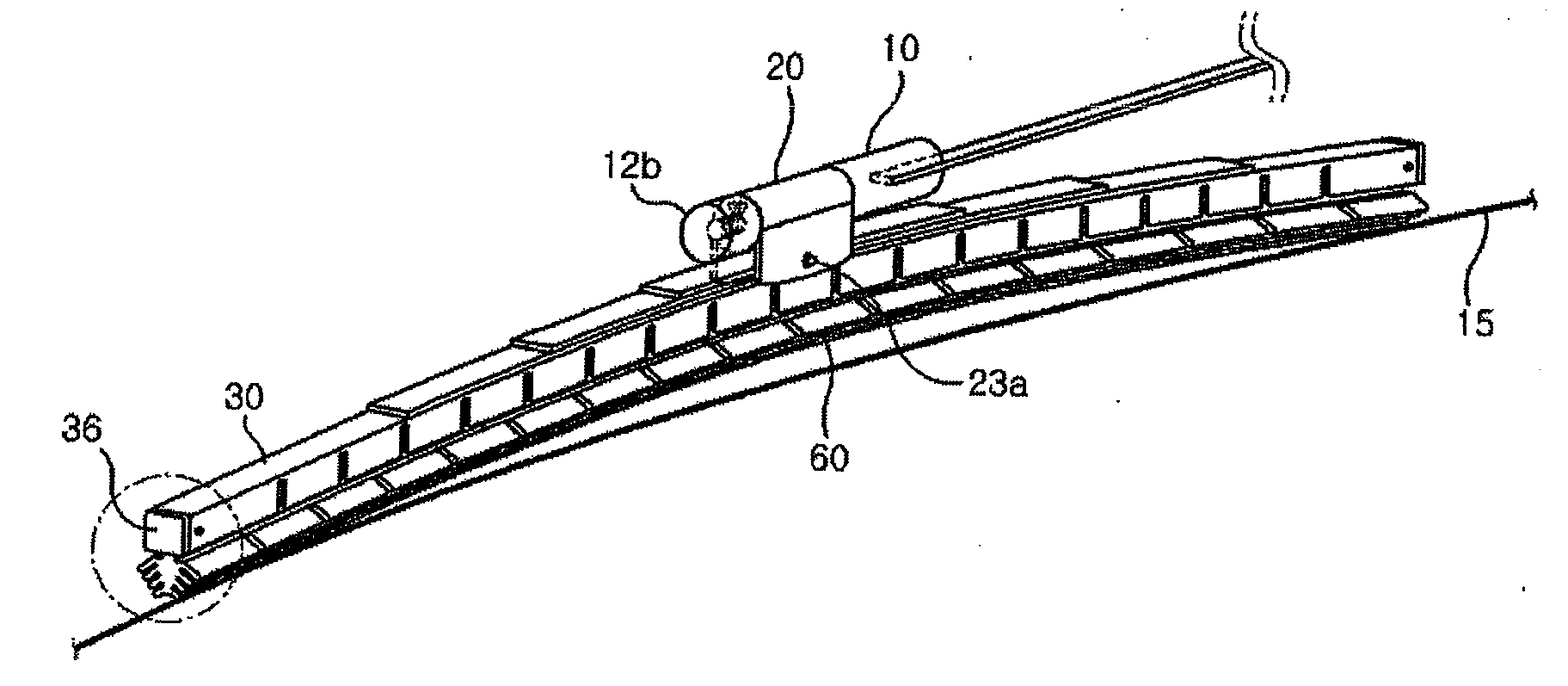
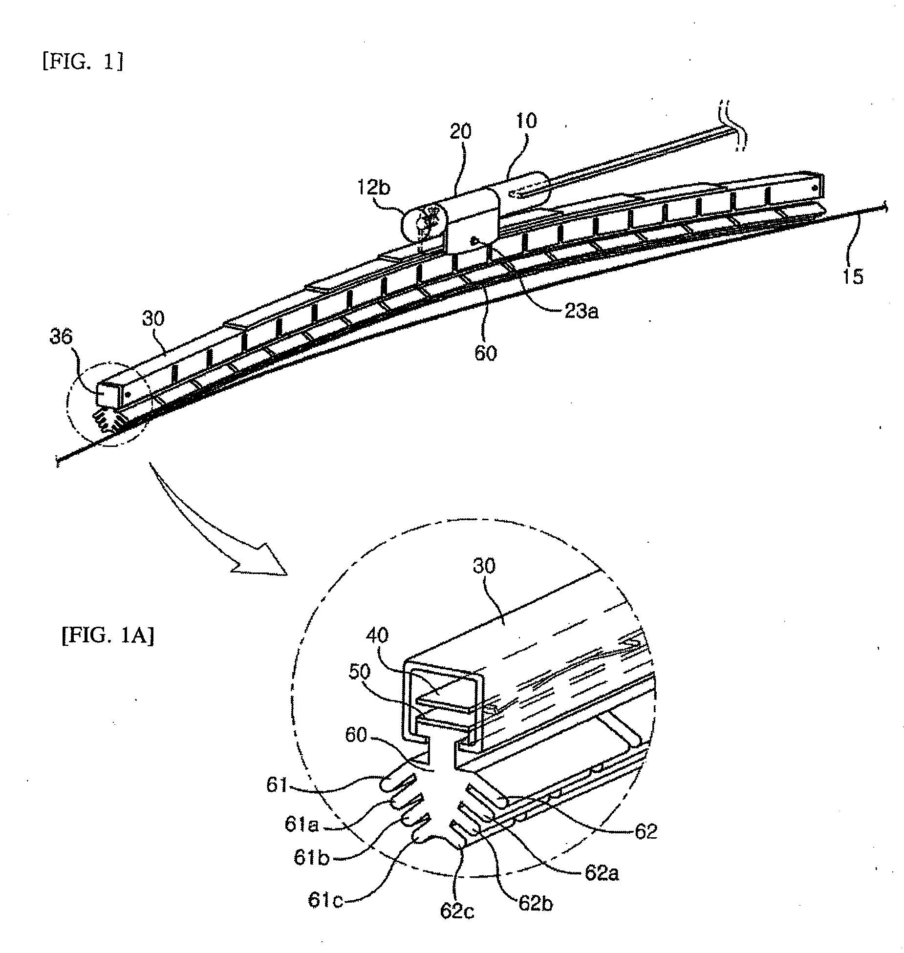
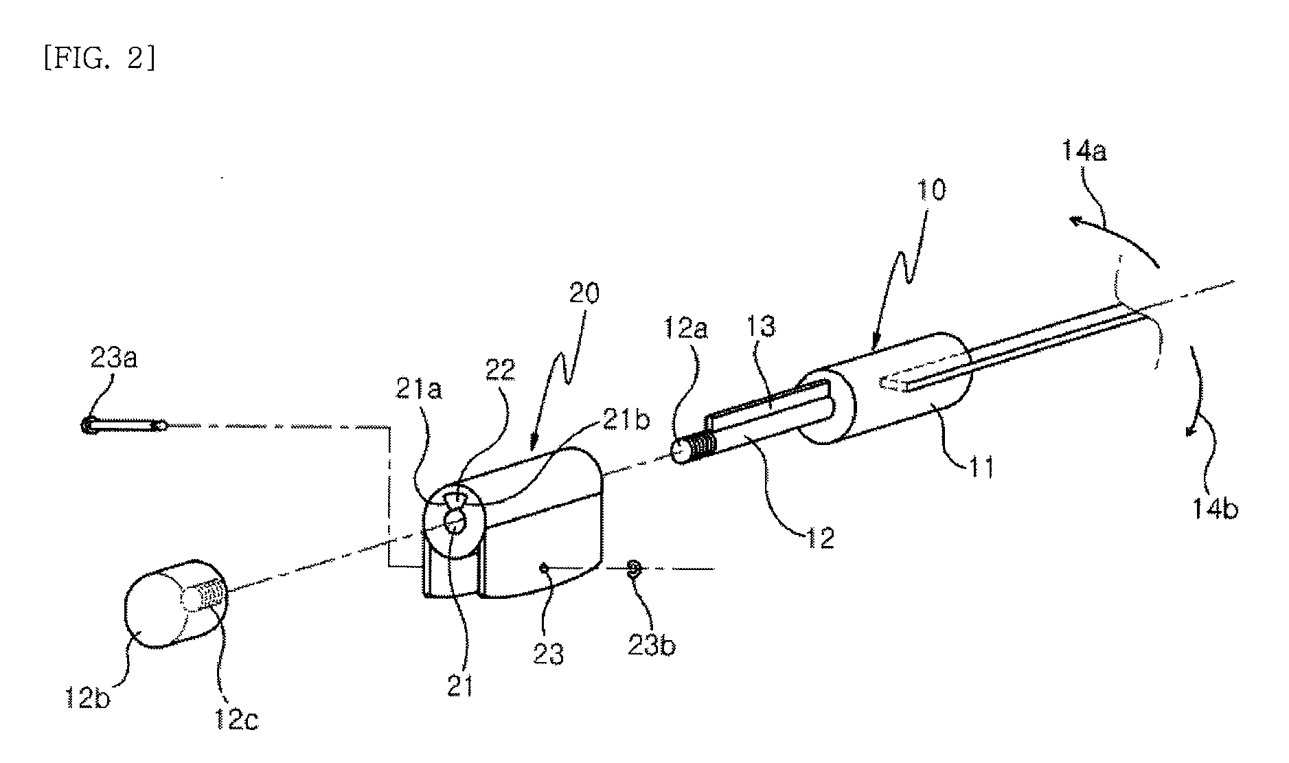
[0027]FIG. 1 is a perspective view of a wiper having a tilting multi-blade 60, according to an embodiment of the present invention. FIG. 1A is an enlarged detail of FIG. 1 with an end cap 36 removed. FIG. 2 is an exploded perspective view of a reciprocating tilting device 20 which conducts a mechanical tilting operation according to the present invention. FIG. 3 is a view illustrating a blade holder 30 of the wiper according to the present invention. FIGS. 4, 5 and 6 respectively are perspective views of a blade compressing plate 40, a friction prevention steel plate 50, and the multi-blade 60 of the wiper. FIG. 7 is a bottom view of the multi-blade 60. FIG. 8 is a view showing the operation of the multi-blade 60 according to a tilting direction.

[0028]As shown in FIGS. 1 and 2, the wiper according to the embodiment of the present invention includes a...


PUM


Abstract

Disclosed herein is a wiper having a tilting multi-blade to wipe a windshield of a transportation means. The wiper includes a wiper arm, a reciprocating tilting device, a blade holder, a multi-blade and a blade compressing plate. The wiper arm has a tilting control stopper. The reciprocating tilting device has a tilting angle control hole into which the tilting control stopper is inserted such that the reciprocating tilting device is rotatable within a limited angular range. The blade holder is coupled to the reciprocating tilting device and has holder compressing plate springs. The blade holder has an elastic notch to provide uniform elastic repulsive force. The multi-blade includes a coupling part which is inserted into the blade holder, and multiple blade lips which are symmetrically provided on left and right sides. The blade compressing plate is inserted into the blade holder and has plate springs to evenly compress the multi-blade.

Description

BACKGROUND OF THE INVENTION[0001]1. Field of the Invention[0002]The present invention relates generally to wipers for removing dirt or rain from windshields and, more particularly, to a wiper having a tilting multi-blade in which a blade holder is sectioned into several parts and provided with a blade compressing unit, so that compression force can be evenly applied to the entire length of a multi-blade such that the multi-blade evenly comes into close contact with a windshield, and in which a reciprocating tilting device conducts a blade tilting operation so that the blade tilting operation can be reliably conducted mechanically, and the blade integrally includes a plurality of blade lips to have a multiple structure, thus ensuring the superior durability of the blade.[0003]2. Description of the Related Art[0004]To date, wipers for vehicles, airplanes and other machines have been developed by various techniques including the following.[0005]First, as shown in FIG. 9 illustrating a ...

Claims


Application Information

Patent Timeline
Patent Type & Authority Applications(United States)
IPC IPC(8): B60S1/38
CPCB60S1/3882B60S1/3886B60S2001/3837B60S2001/3824B60S2001/3812B60S1/38B60S1/48
Inventor JEONG, HYUN CHAN
Owner JEONG HYUN CHAN
Learn More