Cooling Device

a cooling device and cooling technology, applied in the direction of casings/cabinets/drawers, heating types, casings/cabinets/drawers, etc., can solve the problem that the cooling capacity may tend to decline, and achieve the effect of reducing the drop of cooling capacity, and reducing the drop of air flow ra

Active Publication Date: 2010-09-02
PANASONIC CORP +1
View PDF11 Cites 18 Cited by
  • Summary
  • Abstract
  • Description
  • Claims
  • Application Information

AI Technical Summary

Benefits of technology

[0011]The present invention provides a cooling device decreased in drop of air flow rate and drop of cooling capacity due to mounting of control device.
[0012]The heat exchanger of the present invention includes a box body, an indoor air channel, an outdoor air channel, an indoor air blower, an outdoor air blower, a heat exchanger, a control device, and a control device accommodating unit, and the box body is provided in a heating element storing box for storing a heating element, and at least one side is formed by a detachable panel, and the indoor air channel sucks in and circulates the air in the heating element storing box, the outdoor air channel sucks in and circulates the outdoor air, the indoor air blower conveys air into the indoor air channel, the outdoor air blower conveys air into the outdoor air channel, the heat exchanger has an indoor air flow-in port, and exchanges sensible heat between the air in the indoor air channel and the air in the outdoor air channel, the control device controls the indoor air blower and the outdoor air blower, and the control device accommodating unit accommodates the control device. Further, the indoor air blower and the outdoor air blower are installed so that the axial direction of the rotary shaft and the air suction direction may be parallel to each other, and the sensible heat exchanger is disposed at the downstream side of the indoor air blower and the outdoor air blow, and the indoor air flow-in port and the control device accommodating unit are disposed adjacently to the accommodating section of the indoor air blower, and impellers of the indoor air blower are opposite to each other in the sequence of the indoor air flow-in port and the control device accommodating unit, by rotation of the impellers, and a space is further formed between the indoor air flow-in port and the control device accommodating unit. By this configuration, it hence realizes a cooling device decreased in drop of air flow rate and drop of cooling capacity due to mounting of control device.

Problems solved by technology

Therefore, depending on the location of the control device, the air flow rate may be lowered, or the air blowing state to the heat transfer plate may be biased, and the cooling capacity may tend to decline.

Method used


Image

  • Cooling Device
  • Cooling Device
  • Cooling Device

Examples


embodiment 1

Preferred Embodiment 1

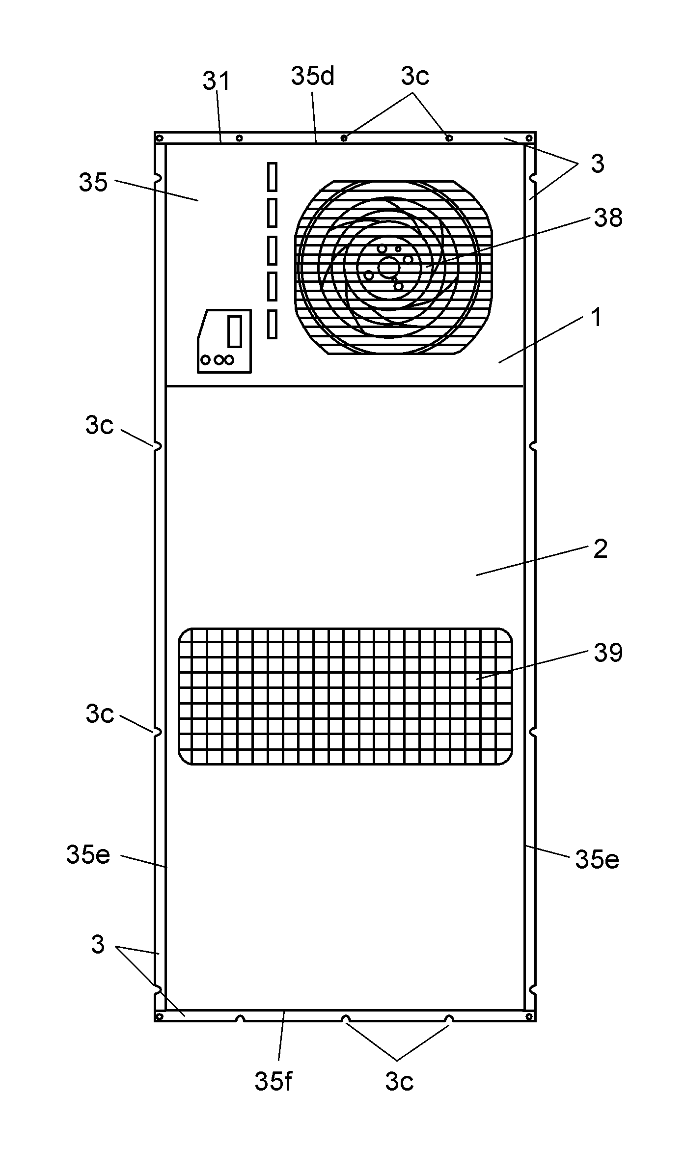
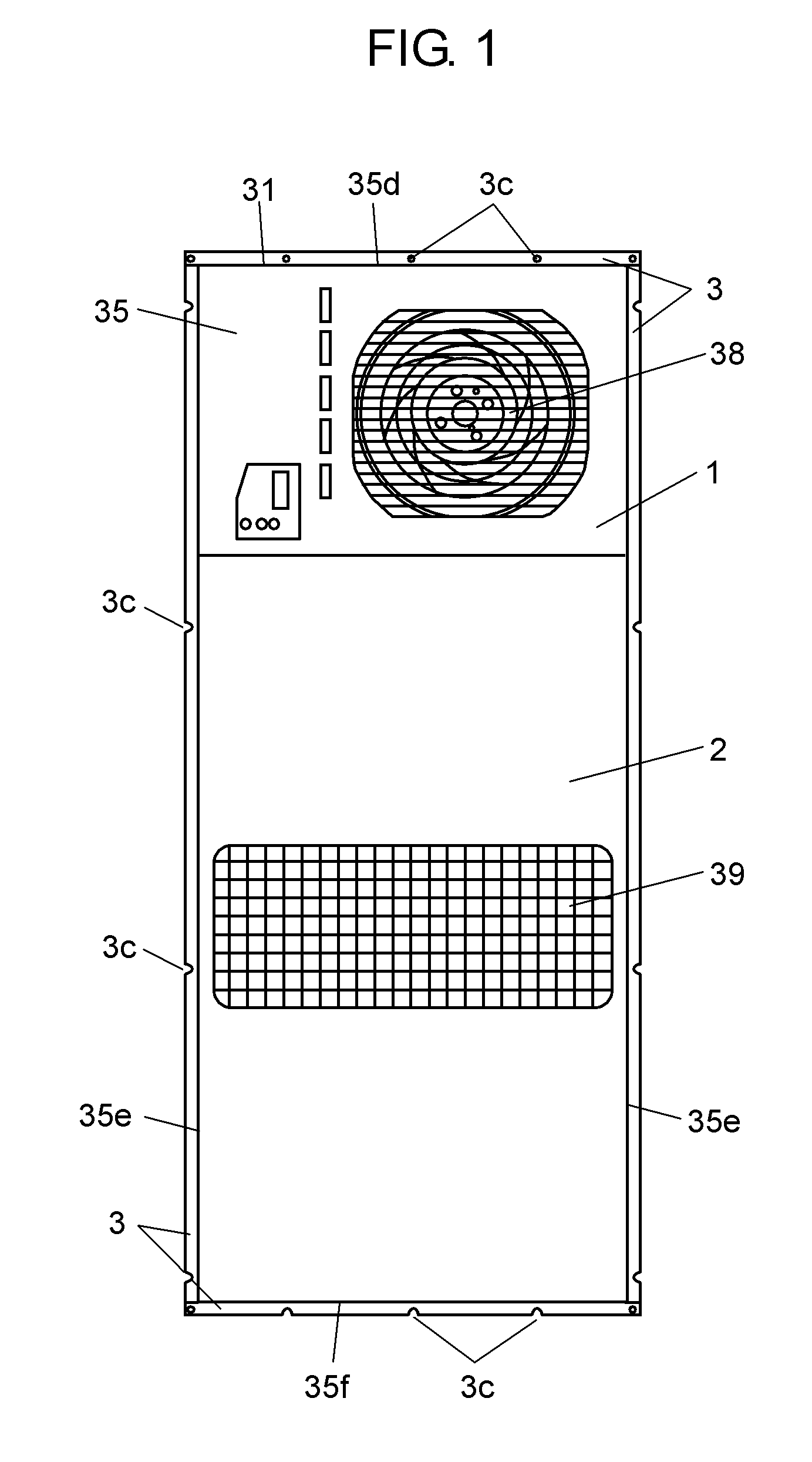
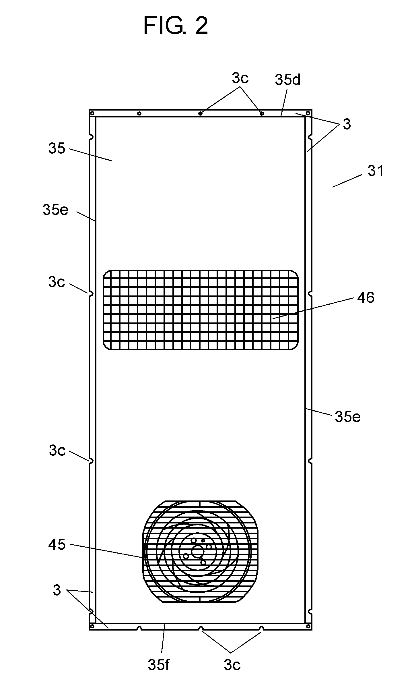
[0079]Preferred embodiment 1 of the present invention is described while referring to FIG. 1 to FIG. 8. FIG. 1 is a front view of cooling device 31 in preferred embodiment 1 of the present invention. FIG. 2 is a rear view of cooling device 31. FIG. 3 is a schematic side structural diagram showing a state of cooling device 31 being installed in heating element storing box 4 (hereinafter called box 4). FIG. 4 is an internal structural diagram of cooling device 31. FIG. 5 is a partial exploded perspective view of heat exchanger 9 of cooling device 31. FIG. 6 is a magnified perspective view of section 50 for accommodating indoor side turbo fan 7 (hereinafter called fan 7) of cooling device 31. FIG. 7 is a schematic perspective view showing a mounting state of indoor air duct 17 (hereinafter called duct 17) of cooling device 31. FIG. 8 is a schematic sectional structural diagram along section line 8-8 of cooling device 31 shown in FIG. 4.

[0080]As shown in FIG. 1 and...

embodiment 2

Preferred Embodiment 2

[0093]Preferred embodiment 2 of the present invention is described below while referring to FIG. 9 and FIG. 10. Same components as in preferred embodiment 1 are identified with same reference numerals, and detailed description is omitted. FIG. 9 is an internal schematic perspective view of controller box 15 in cooling device 31 in preferred embodiment 2 of the present invention. FIG. 10 is a schematic perspective view showing relative positions of indoor air duct 17 and exhaust port 19 of controller box 15.

[0094]As shown in FIG. 9 and FIG. 10, as a flow-in port of control device accommodating unit, intake port 18 of box 15 communicates with same section 50 as blow-out port 52 of fan 7. That is, intake port 18 communicates with section 50 at high pressure side of fan 7, and is also provided near printed board 14a contained in box 15. Printed board 14a is a part of control device 14, and is a heating element which generates a large amount of heat. As a result, pr...

embodiment 3

Preferred Embodiment 3

[0099]Preferred embodiment 3 of the present invention is described below while referring to the drawing. Same components as in preferred embodiments 1 and 2 are identified with same reference numerals, and detailed description is omitted. FIG. 11 is an internal schematic perspective view of controller box 15 in preferred embodiment 3 of the present invention.

[0100]Intake port 18 communicates with section 50 at the high pressure side of fan 7. Further, intake port 18 is provided on back side 15a of box 15 on an extension line linking exhaust port 19 and printed board 14a. Exhaust port 19 communicates with duct 17.

[0101]In this configuration, a part of the air blown out from fan 7 forms air stream 64 to flow from intake port 18 into box 15. The air flowing into box 15 cools printed board 14a, and flows almost straightly into exhaust port 19, and is exhausted from exhaust port 19 to outside of box 15. That is, the air is exhausted into duct 17.

[0102]Printed board ...


PUM


Abstract

A control device accommodating unit (15) is provided in a section (50) accommodating an indoor air blower (7) adjacently to an indoor air flow-in port (16), and an impeller (7c) of the indoor air blower (7) is sequentially opposite to the indoor air flow-in port (16) and the control device accommodating unit (15) by rotation of the impeller (7c), and a space (51) is formed between the indoor air flow-in port (16) and the control device accommodating unit (15). In this configuration, it is possible to obtain a cooling device decreased in drop of air flow rate and drop of cooling performance due to mounting a control device (14).

Description

TECHNICAL FIELD[0001]The present invention relates to a cooling device such as a heating element storing box having a heating element in its inside.BACKGROUND ART[0002]Recently, electronic components are becoming higher in performance and the packing density of electronic components on a control board is becoming higher, and the amount of heat generation from the control board is increasing dramatically. As a result, the internal temperature of the heating element storing box for accommodating electronic components tends to be higher, and the temperature in the heating element storing box has a vital effect on guarantee of operation and product life of electronic components mounted on the control board. It is hence demanded to cool the temperature in the heating element storing box below a specific point by using a cooling device.[0003]Conventionally, this kind of cooling device is known to include a heat transfer plate as a sensible heat exchanger, an indoor air suction fan as an i...

Claims


Application Information

Patent Timeline
Patent Type & Authority Applications(United States)
IPC IPC(8): F28F13/12H05K5/02
CPCF24F12/006F24F13/20Y02B30/563H05K7/206F24F2013/207Y02B30/56
Inventor SHIBATA, HIROSHIYASUI, NOBUYUKIMATSUMOTO, MUTSUHIKOSINZAKI, KOUJIYAMAGUCHI, TOSHIKAZUFUNADA, NAOYUKITUZI, KEISUKESAHASI, TAKAHIROOUSAKA, SATOSHIHAGIMOTO, KEISUKE
Owner PANASONIC CORP
Why Eureka
Try Eureka