Cooling unit, electronic device, and heat sink

a technology of electronic devices and cooling units, applied in the direction of lighting and heating apparatus, instruments, and semiconductor/solid-state device details, etc., can solve the problems of increasing the number of steps the complexity of the unit assembly, and the difficulty of so as to suppress the rise in the temperature of the heat producing member, the effect of reducing the cooling capacity and effectively dischargeing dust and dir

Inactive Publication Date: 2011-11-03
SONY CORP
View PDF10 Cites 19 Cited by
  • Summary
  • Abstract
  • Description
  • Claims
  • Application Information

AI Technical Summary

Benefits of technology

[0015]According to a cooling unit, an electronic device, and a heat sink of an embodiment of the present invention, a heat sink to which an air led from a ventilation path is blown from an air outlet is equipped with a dust and dirt outlet. Further, since a position to provide the dust and dirt outlet is a position corresponding to the flow rate of the air flowing in the case, dust and dirt can be discharged effectively. This enables to prevent that dust and dirt are attached to the case or the heat dissipating fins and that the cooling capacity drops down, and to suppress a rise in temperature of heat producing members, such as a CPU and an IC.
[0016]In addition, a dust entrance prevention material does not have to be equipped and a hole does not have to be opened in a case, so that dust and dirt can be discharged with an extremely simple configuration. As a result, it is also possible to simplify the steps for assembling the unit.

Problems solved by technology

Therefore, there used to be a problem of not only an increase of the number of component items but also an increase of the number of steps when the unit is assembled.
Therefore, when the unit is assembled, a step of not only ramping heat dissipating fins but also forming a dust and dirt outlet in a case is desired, which used to make assembly of the unit complicated.
Therefore, there also used to be a problem that it was difficult to effectively discharge dust and dirt and the dust and dirt remained undischarged were attached to the heat dissipating fins and the cooling capacity of the unit dropped down.

Method used


Image

  • Cooling unit, electronic device, and heat sink
  • Cooling unit, electronic device, and heat sink
  • Cooling unit, electronic device, and heat sink

Examples


embodiment

1. Embodiment

1-1. Configuration of Electronic Device

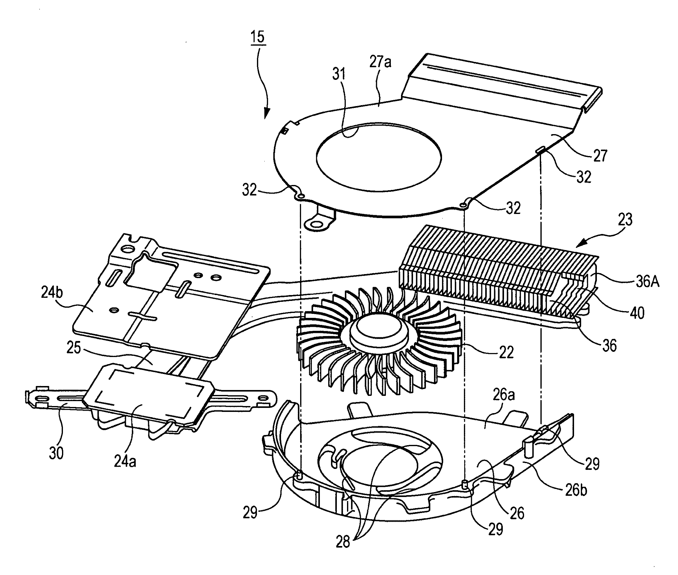
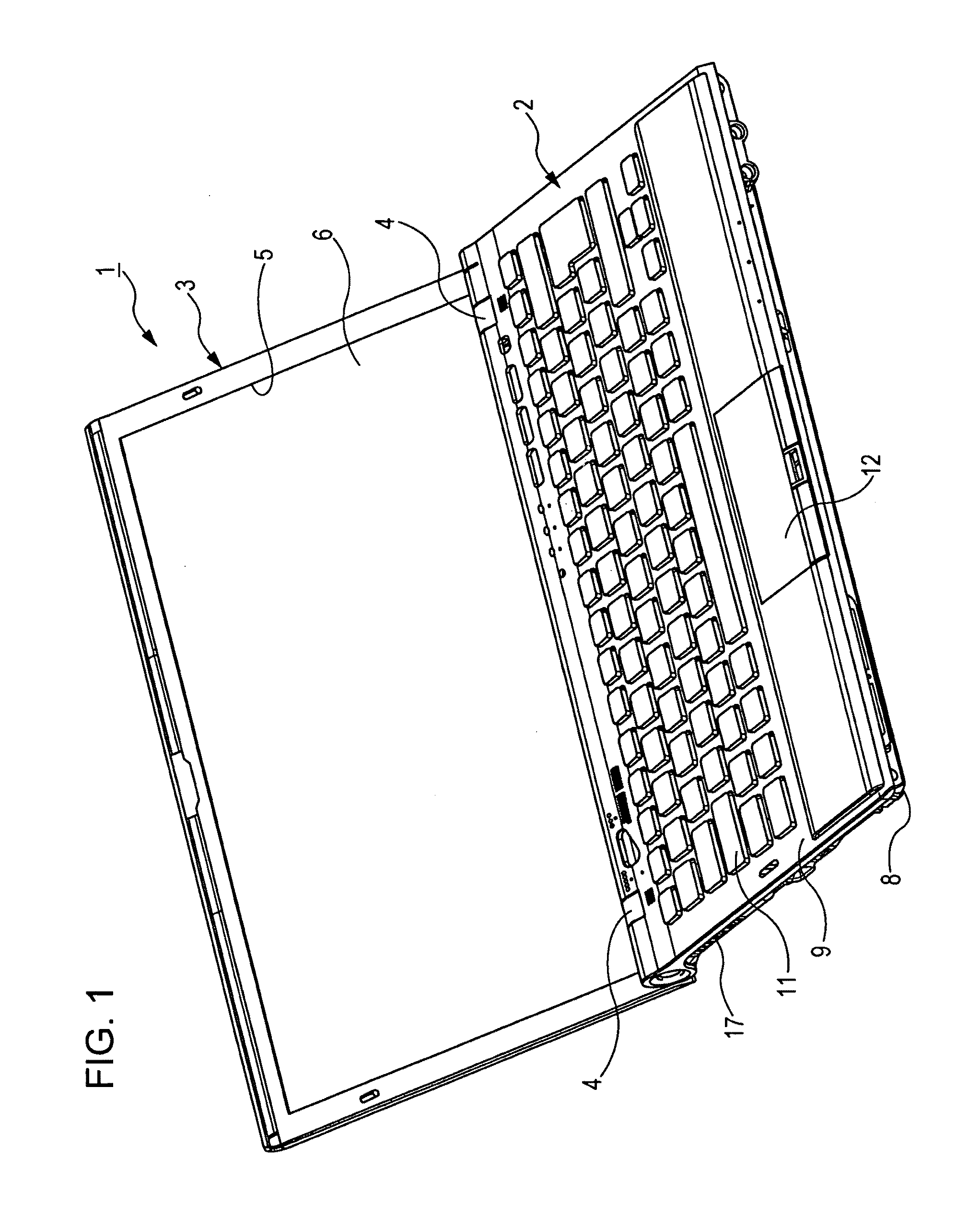
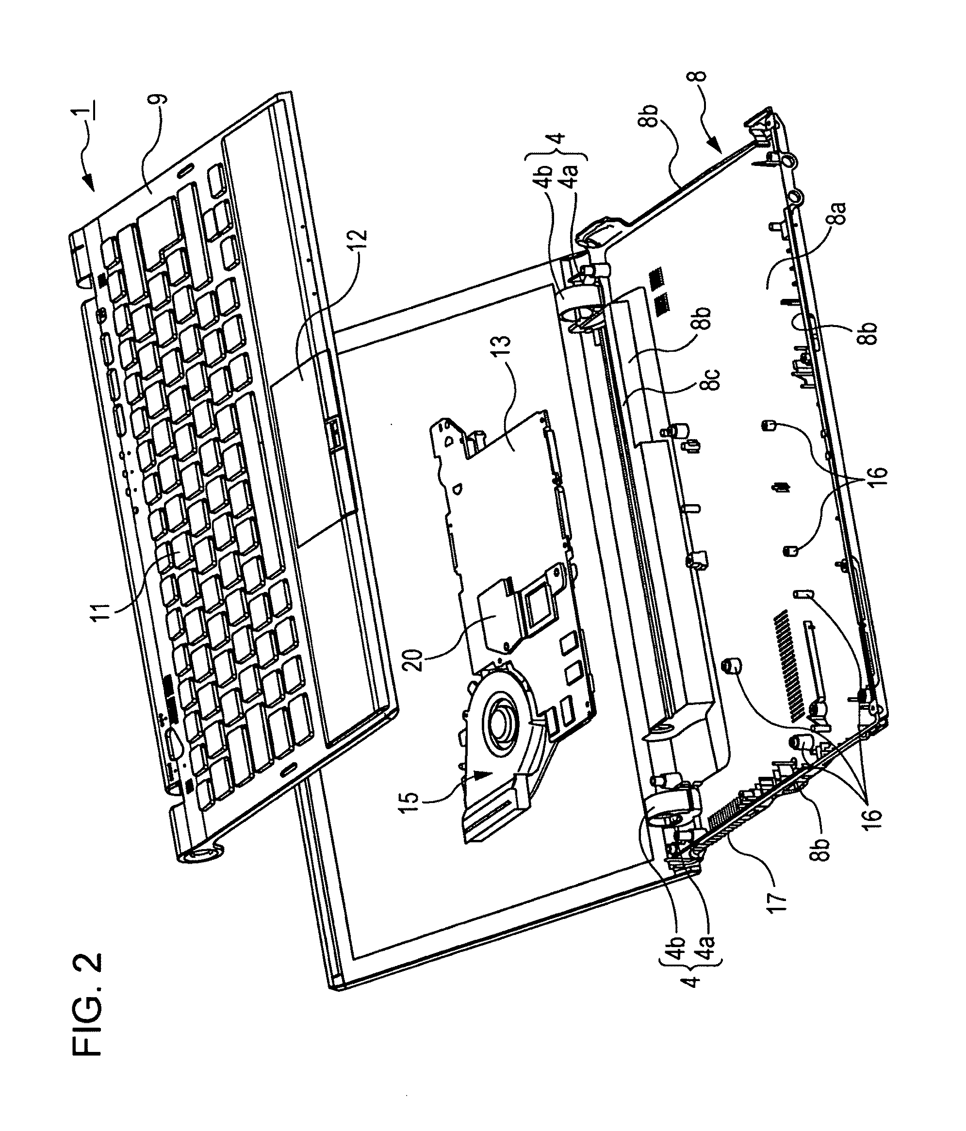
[0035]Firstly, with reference to FIGS. 1 through 4, a description is given to an electronic device according to an embodiment of the present invention.

[0036]FIG. 1 is a perspective view illustrating an electronic device of the embodiment, and FIG. 2 is an exploded perspective view illustrating the electronic device of the embodiment. FIG. 3 is a top view illustrating a main body of the electronic device of the embodiment, and FIG. 4 is a side view illustrating the main body of the electronic device of the embodiment.

[Electronic Device]

[0037]As shown in FIG. 1, an electronic device 1 of the embodiment is a laptop personal computer (hereinafter, referred to as “a laptop PC”). The laptop PC 1 is configured to be provided with a flat perpendicular parallelepiped main body 2, a similarly flat perpendicular parallelepiped display 3, and the like. The main body 2 and the display 3 are provided with a space in a predetermined size respecti...


PUM


Abstract

A cooling unit includes: a case having an air inlet that sucks an air, an air outlet that discharges the sucked air, and a side wall that forms a ventilation path leading the air from the air inlet to the air outlet; a fan housed in the case; and a heat sink arranged in the air outlet of the case, having a plurality of heat dissipating fins, and having a dust and dirt discharging port formed at a position corresponding to a flow rate of the air flowing in the case.

Description

CROSS-REFERENCE TO RELATED APPLICATION[0001]The present application claims priority from Japanese Patent Application No. JP 2010-105835 filed in the Japanese Patent Office on Apr. 30, 2010, the entire content of which is incorporated herein by reference.BACKGROUND OF THE INVENTION[0002]1. Field of the Invention[0003]The present invention relates to a cooling unit that prevents heat dissipating fins from dust clogging by dust and dirt entered in the unit, an electronic device provided with the cooling unit, and a heat sink used for the cooling unit.[0004]2. Description of the Related Art[0005]In the past, in an electronic device such as a personal computer, a cooling unit configured with a heat sink and a fan is used for cooling components that produce heat (hereinafter, referred to as “heat producing components”), such as an IC (integrated circuit) and a CPU (central processing unit). A heat sink is configured with a plurality of heat dissipating fins that are stacked at predetermin...

Claims


Application Information

Patent Timeline
Patent Type & Authority Applications(United States)
IPC IPC(8): H05K7/20F28F13/00
CPCG06F1/203H01L23/467H01L2924/0002H01L2924/00
Inventor OIKE, SHINTSUKAMOTO, TOMOYUKI
Owner SONY CORP
Why Eureka
Try Eureka