A non-liquid immersed transformer

a transformer and liquid immersion technology, applied in transformers/inductance cooling, basic electric elements, electrical equipment, etc., can solve the problems of increasing the footprint and cost of the transformer, increasing the size of the transformer, and not only the footprint of the coil winding but also the whole transformer, so as to reduce the temperature range of use, increase the resistance, and reduce the effect of corrosion

Pending Publication Date: 2022-10-13
HITACHI ENERGY SWITZERLAND AG
View PDF0 Cites 0 Cited by
  • Summary
  • Abstract
  • Description
  • Claims
  • Application Information

AI Technical Summary

Benefits of technology

[0014]In an example, the cooling fluid may have an electric conductivity of less than 5·10−4 S/m which further increases the resistivity to prevent current flow within the cooling fluid.
[0015]In an example, the cooling fluid may be water, e.g. distilled and/or deionised water, the cooling fluid further comprising additives to mitigate corrosion and increase temperature range of usage but maintaining a low electrical conductivity. Additionally, the use of water in the cooling system provides a cost effective, environmentall

Problems solved by technology

However, the cooling capacity of such airflow may not be enough to dissipate the heat.
This solution presents several drawbacks, such as the necessity of using an enclosure thereby increasing the footprint and the cost of the transformer.
The use of those metallic pipes involve several drawbacks: such hollow conductor pipes require an extra space in order to accommodate the conduit, i.e. to permit enough cooling fluid flow, and thus, the size i.e. the footprint, not only of the coil winding but also of the whole transformer is substantially increased.
In addition, such special winding pipes are difficult to manufacture and expensive.
Furthermore, the relatively large size of these hollow conductors creates a considerable i

Method used


Image

  • A non-liquid immersed transformer
  • A non-liquid immersed transformer

Examples


Embodiment Construction

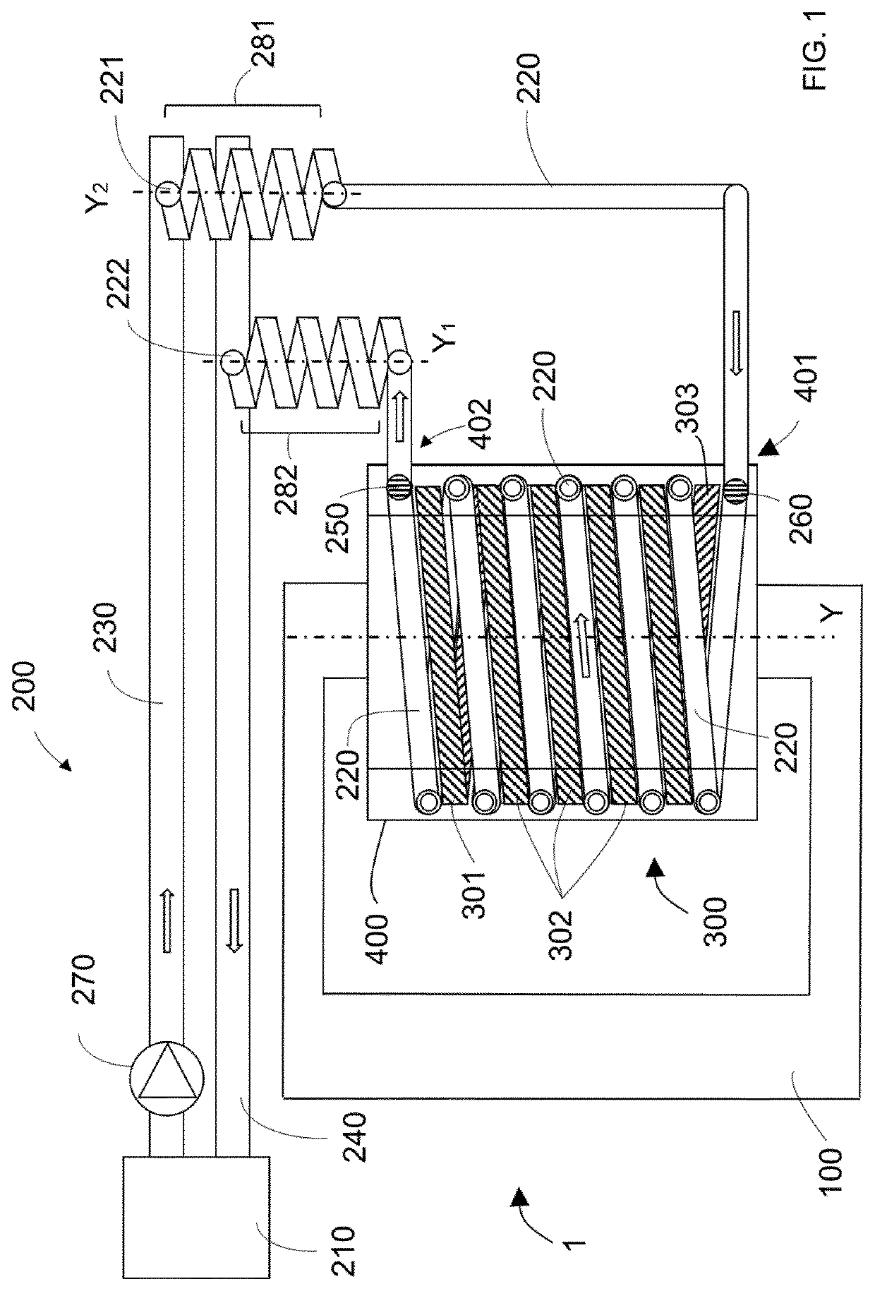
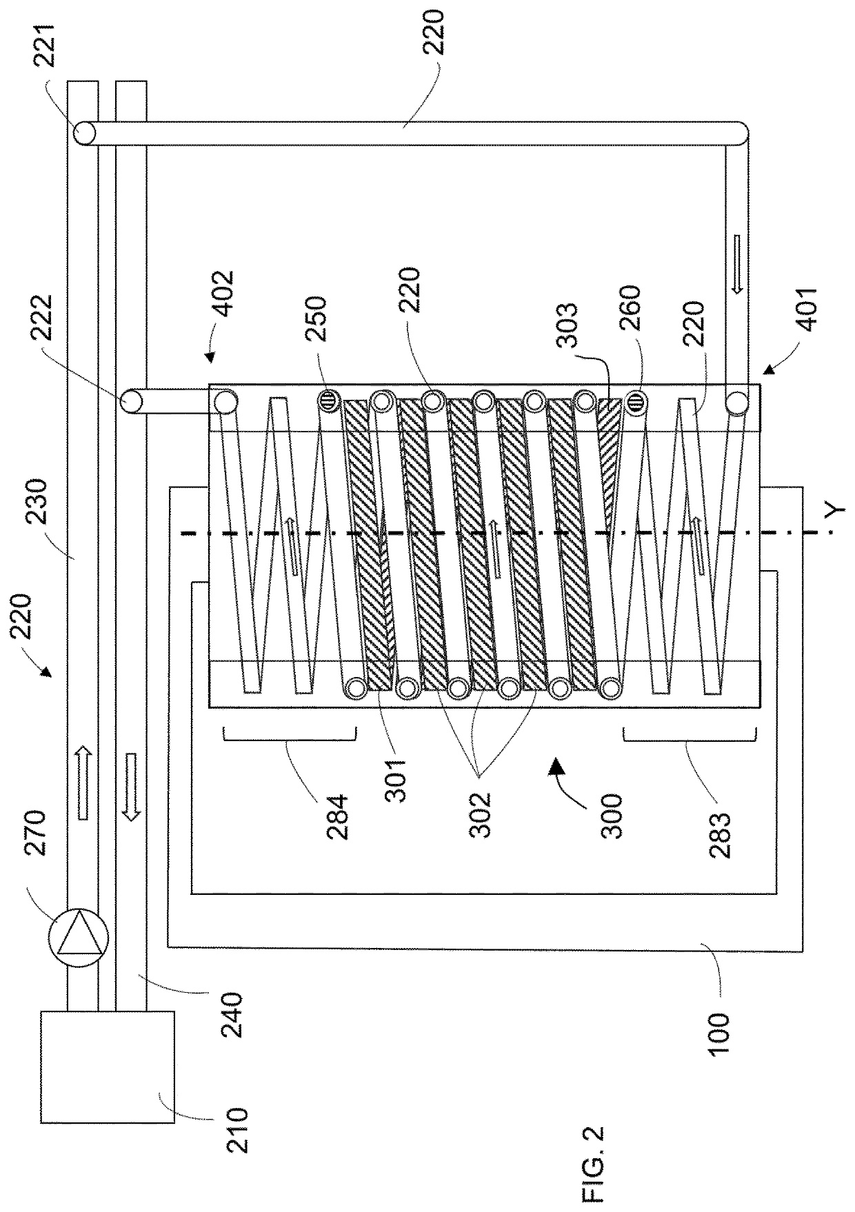
[0023]FIG. 1 depicts a dry-type transformer 1 comprising a magnetic core 100 which may comprise at least a coil winding 300 around axis Y, and a cooling system 200.

[0024]The coil winding 300 may form a plurality of turns (shown in striped lines) around the magnetic core 100: a first turn 301, i.e. the beginning of winding; a plurality of intermediate turns 302 and a last turn 303, i.e. the termination of the winding. The coil winding 300 may therefore comprise two ends, i.e. portions of the winding encompassing the first turn and the last turns of the coil winding, respectively.

[0025]The coil winding 300 may be made of conductive materials e.g. copper or aluminium, that may be covered or coated with an insulating dielectric material such as polyester or epoxy resin, except in the ends in which part of the winding may need to be accessed e.g. to connect a cable to output the generated voltage.

[0026]Despite a single-phase magnetic core is depicted in FIG. 1, the transformer 1, in an e...


PUM


Abstract

A non-liquid immersed transformer is provided. The transformer includes a magnetic core and a coil winding forming a plurality of winding turns around the magnetic core and a cooling system. The cooling system includes a heat exchanger, a main feeding pipe and a main return pipe, and a cooling pipe for the flow of a cooling fluid. The cooling pipe extends at least partly along the coil winding between a first point adjacent to an end of the coil winding, and a second point adjacent to the other end of the coil winding. The cooling pipe also includes a plurality of convolutions to extend the path of the cooling fluid between one end of the winding and one of the main feeding pipe and the main return pipe.

Description

CROSS REFERENCE TO RELATED APPLICATIONS[0001]This application is a 35 U.S.C. § 371 national stage application of PCT International Application No. PCT / EP2020 / 072699 filed on Aug. 13, 2020, which in turn claims foreign priority to European Patent Application No. 19382713.6, filed on Aug. 14, 2019, the disclosures and content of which are incorporated by reference herein in their entirety.[0002]The present disclosure is related to transformers, more specifically to non-liquid immersed transformers comprising a fluid cooling system.BACKGROUND ART[0003]In order to cool down a transformer, some systems use a gas, e.g. air, to refrigerate the winding or coils thereof. Such air cooling may be forced or natural. In case of forced-air cooling, the blowing equipment e.g. a fan, may be positioned to blow the airflow to the windings. However, the cooling capacity of such airflow may not be enough to dissipate the heat.[0004]It is also known to refrigerate non-liquid immersed transformers using ...

Claims


Application Information

Patent Timeline
IPC IPC(8): H01F27/16H01F27/28
CPCH01F27/16H01F27/2876H01F27/10H01F27/306
Inventor NOGUÉS BARRIERAS, ANTONIOMURILLO, RAFAELROY MARTIN, CARLOSCEBRIÁN LLES, LORENA
Owner HITACHI ENERGY SWITZERLAND AG
Why Eureka
Try Eureka