Thermionic emission device

a technology of emission device and thermionic electron, which is applied in the manufacture of electrode systems, tubes with electrostatic control, and electric discharge tubes/lamps. it can solve the problems of limiting the application of micro-devices, the inability of assembled thermionic emission devices to realize uniform thermionic emission, and the inability to assemble a plurality of thermionic electron emission units

Active Publication Date: 2009-07-02
TSINGHUA UNIV +1
View PDF2 Cites 84 Cited by
  • Summary
  • Abstract
  • Description
  • Claims
  • Application Information

AI Technical Summary

Problems solved by technology

However, it is hard to assemble a plurality of thermionic electron emission units, and the assembled thermionic emission device cannot realize uniform thermionic emission.
Further, the size of the thermionic emitter using the metal, boride, or alkaline earth metal carbonate is large, and thereby limits its application in micro-

Method used


Image

  • Thermionic emission device
  • Thermionic emission device
  • Thermionic emission device

Examples


Embodiment Construction

[0016]References will now be made to the drawings to describe, in detail, embodiments of the present thermionic emission device and method for making the same.

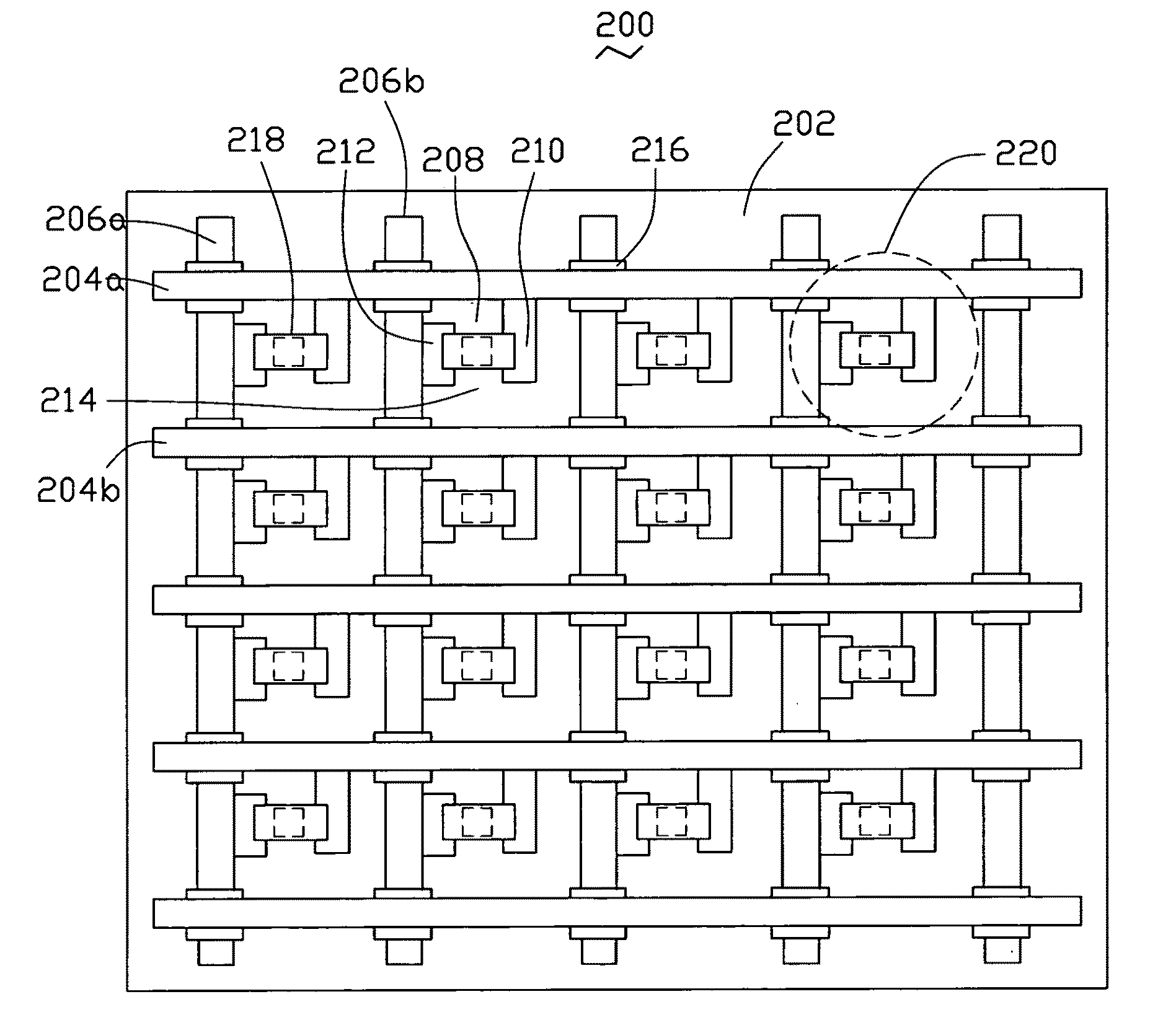
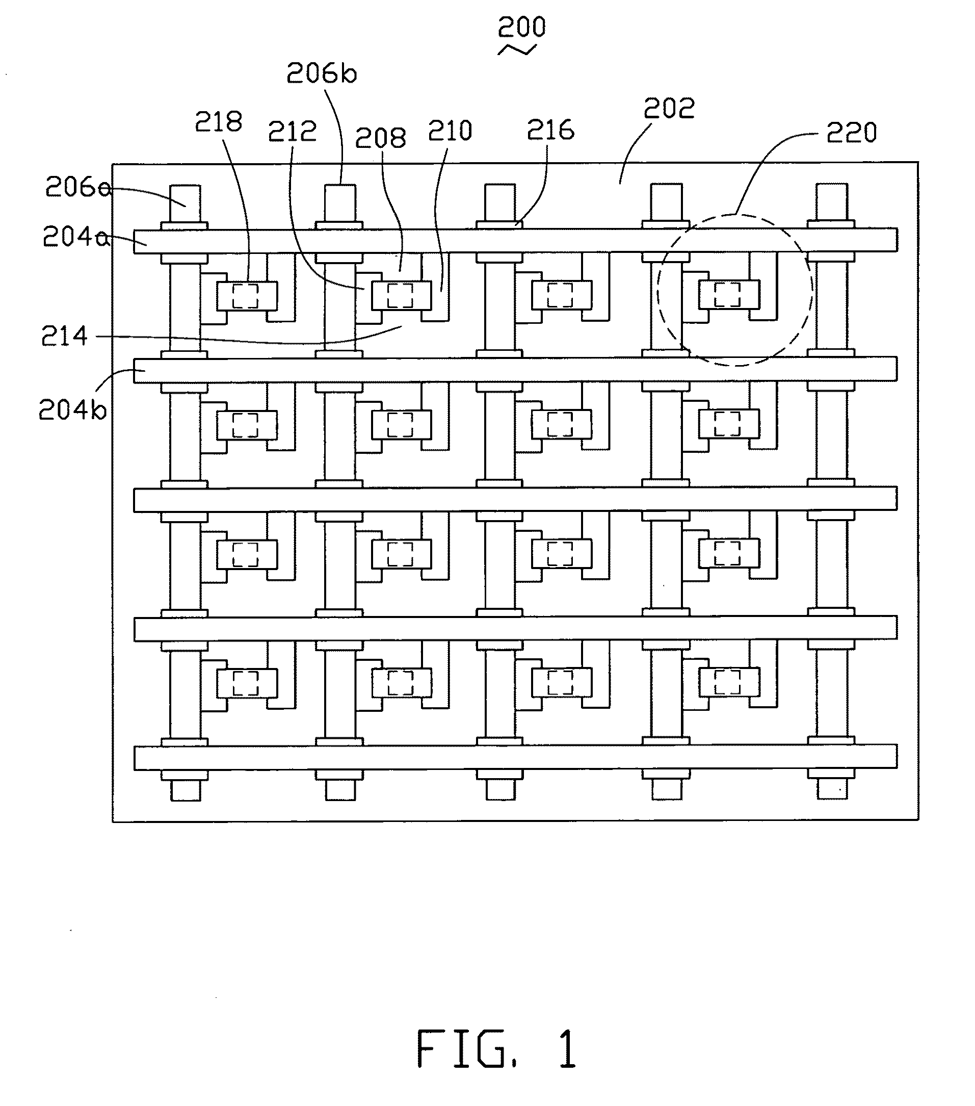
[0017]Referring to FIG. 1, a thermionic emission device 200 includes an insulating substrate 202, and one or more grids 214 located thereon. The insulating substrate 202 includes one or more uniformly-spaced recesses 218. The recesses 218 are insulated. Each grid 214 includes a first electrode down-lead 204a, a second electrode down-lead 204b, a third electrode down-lead 206a, a fourth electrode down-lead 206b located on the periphery of the gird 214, and a thermionic electron emission unit 220 located in each grid 214. The first electrode down-lead 204a and the second electrode down-lead 204b are parallel to each other. The third electrode down-lead 206a and the fourth electrode down-leads 206b are parallel to each other. Furthermore, a plurality of insulating layers 216 is sandwiched between the first and second electrode do...


PUM


Abstract

A thermionic emission device includes an insulating substrate, and one or more grids located thereon. Each grid includes a first, second, third and fourth electrode down-leads located on the periphery thereof, and a thermionic electron emission unit therein. The first and second electrode down-leads are parallel to each other. The third and fourth electrode down-leads are parallel to each other. The first and second electrode down-leads are insulated from the third and fourth electrode down-leads. The thermionic electron emission unit includes a first electrode, a second electrode, and a thermionic electron emitter. The first electrode and the second electrode are separately located and electrically connected to the first electrode down-lead and the third electrode down-lead respectively. The insulating substrate comprises one or more recesses that further insulate the thermionic electron emitters from the substrate.

Description

RELATED APPLICATIONS[0001]This application is related to commonly-assigned applications entitled, “METHOD FOR MAKING THERMIONIC ELECTRON SOURCE”, filed ______ (Atty. Docket No. US18567); “THERMIONIC ELECTRON SOURCE”, filed ______ (Atty. Docket No. US18568); “THERMIONIC EMISSION DEVICE”, filed ______ (Atty. Docket No. US18570); “THERMIONIC ELECTRON EMISSION DEVICE AND METHOD FOR MAKING THE SAME”, filed ______ (Atty. Docket No. US18569); and “THERMIONIC ELECTRON SOURCE”, filed ______ (Atty. Docket No. US17306). The disclosures of the above-identified applications are incorporated herein by reference.BACKGROUND[0002]1. Field of the Invention[0003]The present invention relates to a thermionic emission device adopting carbon nanotubes and a method for making the same.[0004]2. Discussion of Related Art[0005]Carbon nanotubes (CNT) are a carbonaceous material and have received much interest since the early 1990s. Carbon nanotubes have interesting and potentially useful electrical and mechan...

Claims


Application Information

Patent Timeline
IPC IPC(8): H01J1/46
CPCH01J1/13H01J1/15H01J2329/0402H01J31/127H01J29/04
Inventor LIU, PENGLIU, LIANGJIANG, KAI-LIFAN, SHOU-SHAN
Owner TSINGHUA UNIV
Why Eureka
Try Eureka