[0010]In view of the problems with the prior art described above, this invention has been realized. The invention has an object to provide an electrical connector which complies with requirements for narrower pitches of conductors, for
miniaturization, and for reduced overall height of the connector. The connectors are capable of sufficiently holding electrical connections with excellent durability against accidental forces when being fitted together and are also capable of providing power supply connections without using a plural number of terminals.
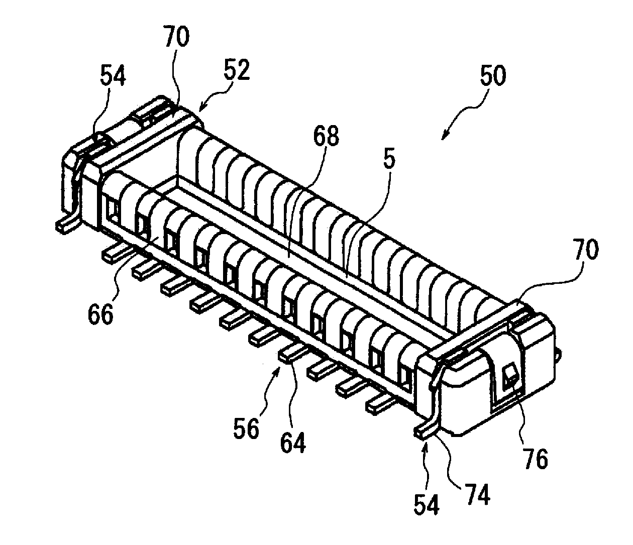
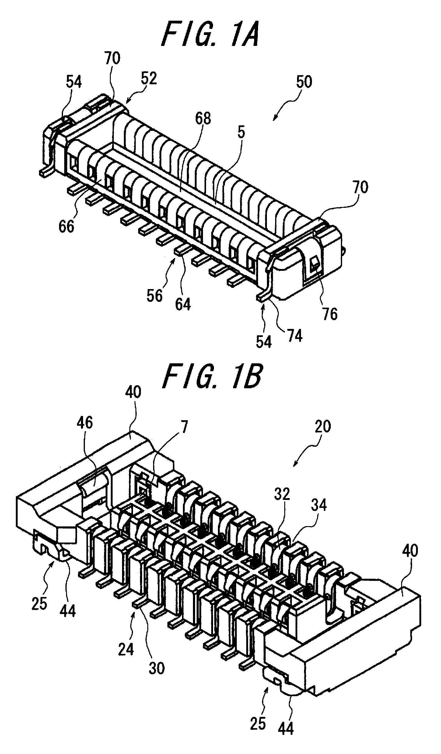
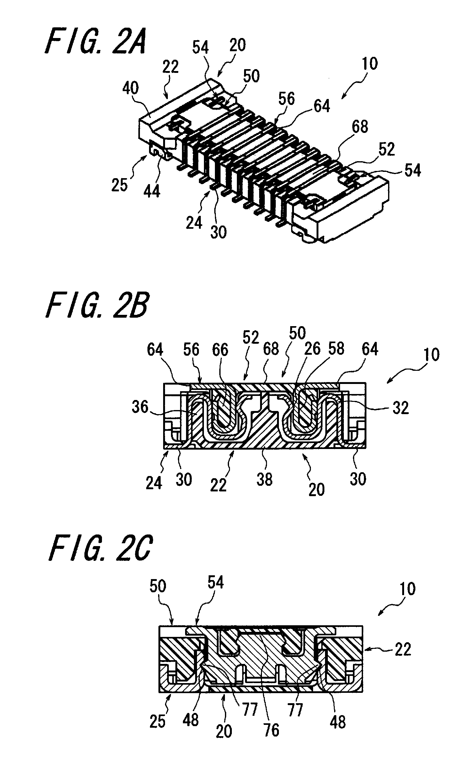
[0017](1) The electrical connector for connecting substrates includes a plug connector and a receptacle connector to be detachably fitted with each other. Said receptacle connector includes a plurality of receptacle contacts and a block for arranging and holding said receptacle contacts. Said receptacle contacts each have a first contact portion adapted to contact a
mating contact, a first fixed portion to be fixed to said block, and a first connection portion to be connected to one of said substrates. Said plug connector includes a plurality of plug contacts and a housing for arranging and holding said plug contacts. Said plug contacts each have a second contact portion adapted to contact said receptacle contact, a second fixed portion to be fixed to said housing. A second connection portion to be connected to the other of said substrates claimed in claim 1 is constructed such that said plug connector and said receptacle connectors are provided with a first fixture and a second fixture each arranged on at least one end in the longitudinal direction of the respective connector. Said first fixture and said second fixture each have connection portions to be connected to said substrate of the respective connector. One of said first and second fixtures is provided with at least three engaging portions, and the other of said fixtures is provided with at least three anchoring portions, respectively. Said engaging portions and said anchoring portions are adapted to engage each other, and at least one set of said engaging and anchoring portions engaged with each other is caused to be in electrical continuity, thereby using them as power supply contacts. Therefore, the electrical connector according to the invention can achieve narrower pitches of conductors and miniaturization and reduced overall height of the connector, and can ensure stable electrical connections because of engagements of the fixtures at three locations even while being subjected to accidental forces when being fitted. The electrical connector can provide a stable power supply connection by causing at least one set of the engaging portion of the fixtures to be in electrical continuity without using a number of terminals.
[0018](2) The electrical connector claimed in claim 2 is constructed such that said engaging portions and said anchoring portions are provided at three locations on said first and second fixtures at the center and at both ends in the width direction of the first and second fixtures, respectively. Accordingly, the electrical connector according to the invention claimed in claim 2 can achieve narrower pitches of conductors and miniaturization and reduced overall height of the connector, and can ensure stable electrical connections because of engagements of the fixtures at three locations even if being subjected to accidental forces when being fitted. The electrical connector can utilize a stable power supply connector by causing at least one set of the engaging portion of the fixtures to be in electrical continuity without using a number of terminals. Since the first engaging portions and the first anchoring portions of the first and second fixtures are located substantially at the center in the width direction of the fixture or the connectors, even if accidental forces acting on the connectors in the longitudinal direction are increased, the engagements of these engaging and anchoring portions do not disengage. Thus, such a rigid engagement portion is caused to be in electrical continuity, thereby enabling the engagement portion to be used as a
power supply unit. Further, since the second engaging portions and the second anchoring portions of the first and second fixtures are located substantially on both ends in the width direction of the fixtures or the connectors, even if accidental forces acting on the connectors in the width direction are increased, the engagements of these engaging and anchoring portions do not disengage. Thus, such a rigid engagement portion is caused to be in electrical continuity, thereby enabling the engagement portion to be used as a
power supply unit.
[0020](4) The electrical connector claimed in claim 4 is constructed such that the first engaging portion of said first fixture is formed as a protrusion. Said second engaging portions are formed as projecting portions projecting outwardly. The first anchoring portion of said second fixture is formed as a plate-shaped portion having a substantially U-shaped cross-section adapted to engage said protrusion. Said second anchoring portions are formed as recesses adapted to accommodate said projecting portions, respectively. Accordingly, the electrical connector according to the invention claimed in claim 4 can achieve narrower pitches of conductors and miniaturization and reduced overall height of the connector, and can ensure stable electrical connections because of engagements of the fixtures at three locations even if being subjected to accidental forces when being fitted. The electrical connector can also provide a stable power supply connection by causing at least one set of the engaging portion of the fixtures to be in electrical continuity without using a number of terminals and contacts. Since the first engaging portions and the first anchoring portions of the first and second fixtures are located substantially at the center in the width direction of the fixtures or the connectors, even if accidental forces acting on the connectors in the longitudinal direction are increased, the engagements of these engaging and anchoring portions do not disengage. Thus, such a rigid engagement portion is caused to be in electrical continuity, thereby enabling the engagement portion to be used as a power supply connector. Further, since the second engaging portions and the second anchoring portions of the first and second fixtures are located substantially on both ends in the width direction of the fixtures or the connectors, even if accidental forces acting on the connectors in the width direction are increased, the engagements of these engaging and anchoring portions do not disengage. Thus, such a rigid engagement portion is caused to be in electrical continuity, thereby enabling the engagement portion to be used as a power supply connector as well.
[0021](5) The electrical connector claimed in claim 5 is constructed such that the first engaging portion of said first fixture and the second anchoring portions of said second fixtures each have an elasticity. Therefore, the electrical connector according to the invention claimed in claim 5 can achieve narrower pitches of conductors and miniaturization and reduced overall height of the connector, and can ensure stable electrical connections because of engagements of the fixtures at three locations even if being subjected to accidental forces when being fitted. The electrical connector can be utilized as a stable power supply connector by causing at least one set of the engaging portion of the fixtures to be in electrical continuity without using a number of terminals or contacts. Since the first engaging portions and the first anchoring portions of the first and second fixtures are located substantially at the center in the width direction of the fixtures or the connectors, even if accidental forces acting on the connectors in the longitudinal direction are increased, the engagements of these engaging and anchoring portions do not disengage. Thus, such a rigid engagement portion is caused to be in electrical continuity, thereby enabling the engagement portion to be used as a power supply connector. Further, since the second engaging portions and the second anchoring portions of the first and second fixtures are located substantially on both ends in the width direction of the fixtures or the connectors, even if accidental forces acting on the connectors in the width direction are increased, the engagements of these engaging and anchoring portions do not disengage, and such a rigid engagement portion is caused to be in electrical continuity, thereby enabling the engagement portion to be used as a power supply connector.

