
Rotating substrate support and methods of use

a technology of rotating substrates and support plates, which is applied in the direction of liquid surface applicators, coatings, chemical vapor deposition coatings, etc., can solve the problems of non-uniform heat distribution profiles within the chamber, difficult to maintain a uniform deposition profile on the substrate, and inability to uniformly deposition materials on the substra

Inactive Publication Date: 2010-09-09
APPLIED MATERIALS INC
View PDF40 Cites 245 Cited by
  • Summary
  • Abstract
  • Description
  • Claims
  • Application Information

AI Technical Summary

Benefits of technology

The rotating substrate support system achieves improved film thickness uniformity, reduces contamination, and allows for optimized deposition rates by averaging temperature and flow inhomogeneities, thereby enhancing the quality and reliability of semiconductor processing.

Problems solved by technology

Due to the flow pattern of the gases introduced into the process chamber towards the pumping port, it is difficult to maintain a uniform deposition profile on the substrate.
In addition, variance in the emissivity of the internal chamber components leads to non-uniform heat distribution profiles within the chamber and, therefore, on the substrate.
Such non uniformities in the heat distribution profile across the surface of the substrate further leads to non uniformities in the deposition of materials on the substrate.
This, in turn, leads to further costs incurred in planarizing or otherwise repairing the substrate prior to further processing or possible failure of the integrated circuit all together.

Method used


Image

  • Rotating substrate support and methods of use
  • Rotating substrate support and methods of use
  • Rotating substrate support and methods of use

Examples


Embodiment Construction

[0015]One exemplary process chamber suitable for use with a rotating substrate support as described herein is a low pressure thermal chemical vapor deposition reactor, such as, for example, a SiNgen chamber, available from Applied Materials, Inc., of Santa Clara, Calif. It is contemplated that other process chambers may also benefit from the use of the rotating substrate support described herein.

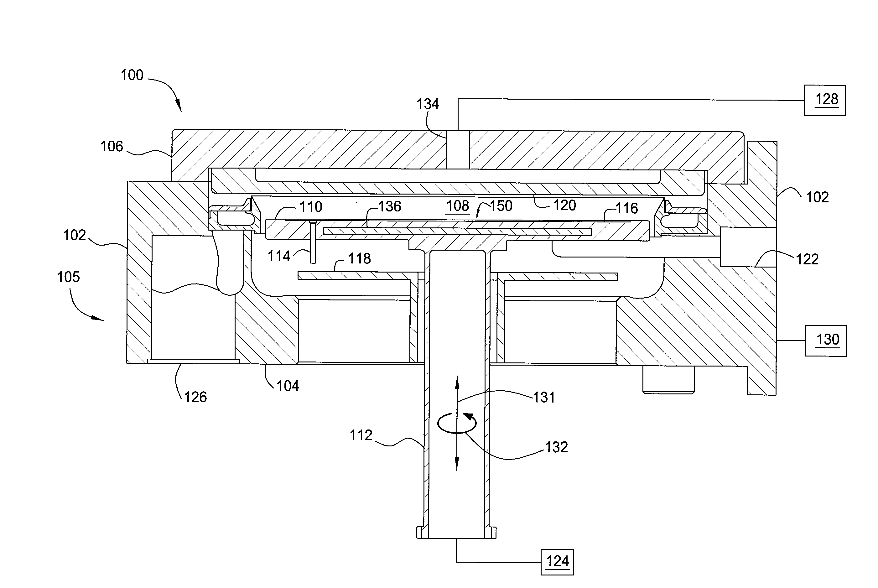
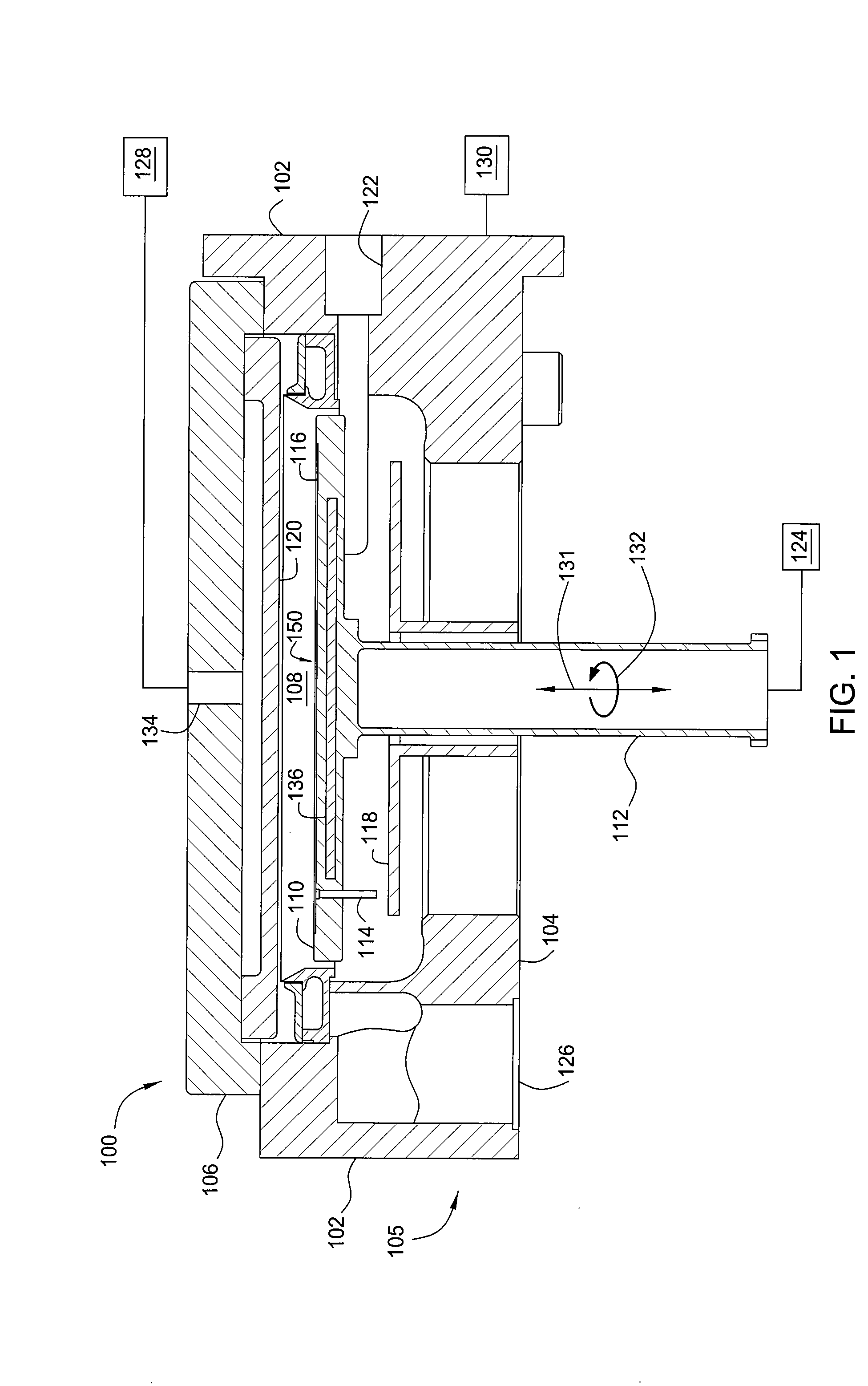
[0016]FIG. 1 illustrates one embodiment of a suitable reactor 100. The reactor 100 comprises a base 104, walls 102, and a lid 106 (collectively referred to as a chamber body 105) that define a reaction chamber, or process volume 108, in which process gases, precursor gases, or reactant gases are thermally decomposed to form a layer of material on a substrate (not shown).

[0017]At least one port 134 is formed in the lid and is coupled to a gas panel 128 that supplies one or more gases to the process volume 108. Typically, a gas distribution plate, or showerhead 120, is disposed beneath the lid...


PUM

PropertyMeasurementUnit
pressuresaaaaaaaaaa
distanceaaaaaaaaaa
diameteraaaaaaaaaa

Abstract

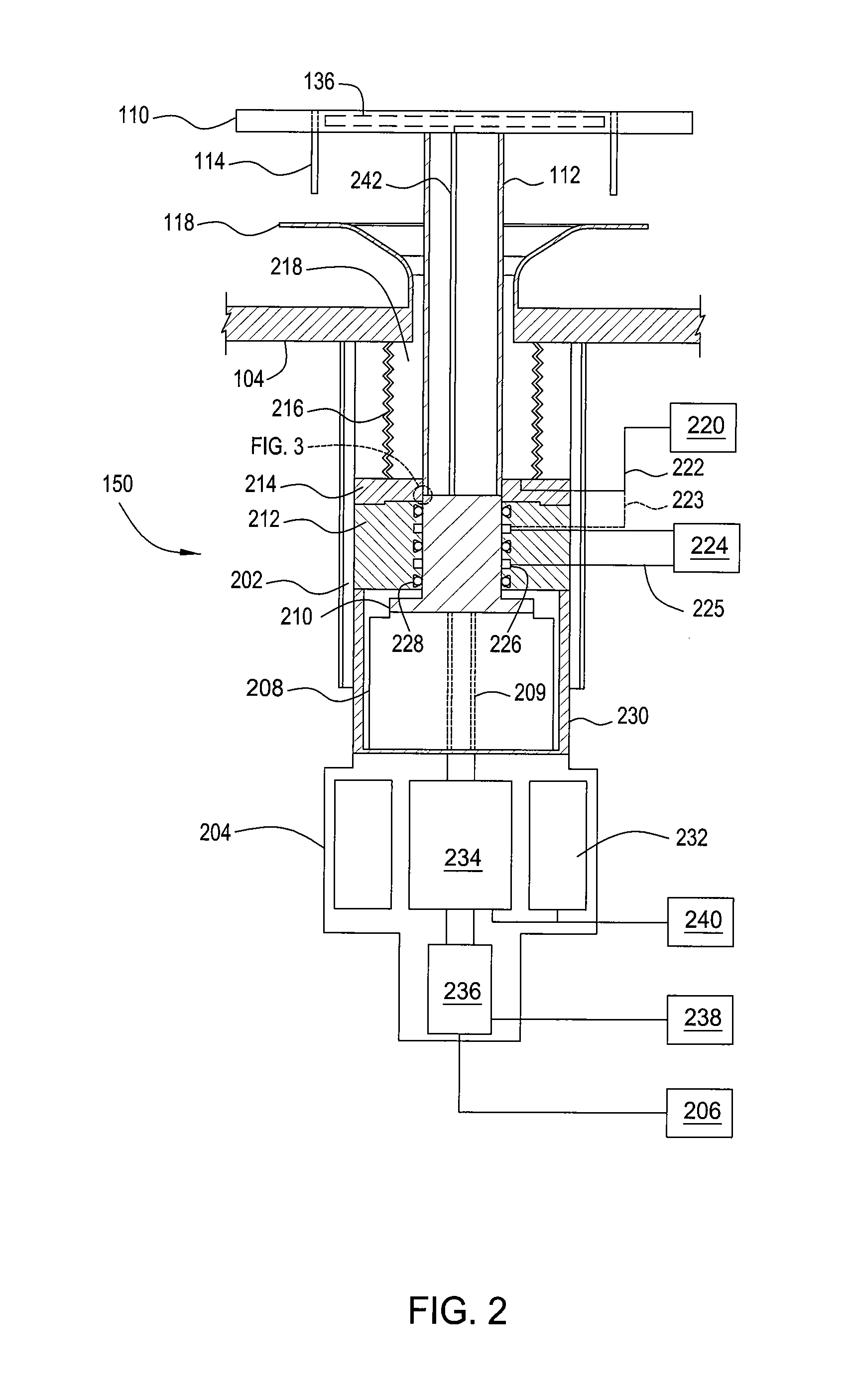
A method and apparatus for processing a substrate utilizing a rotating substrate support are disclosed herein. In one embodiment, an apparatus for processing a substrate includes a chamber having a substrate support assembly disposed within the chamber. The substrate support assembly includes a substrate support having a support surface and a heater disposed beneath the support surface. A shaft is coupled to the substrate support and a motor is coupled to the shaft through a rotor to provide rotary movement to the substrate support. A seal block is disposed around the rotor and forms a seal therewith. The seal block has at least one seal and at least one channel disposed along the interface between the seal block and the shaft. A port is coupled to each channel for connecting to a pump. A lift mechanism is coupled to the shaft for raising and lowering the substrate support.

Description

CROSS-REFERENCE TO RELATED APPLICATIONS[0001]This application is a divisional application of U.S. application Ser. No. 11 / 147,938, filed Jun. 8, 2005, which is incorporated herein by reference.BACKGROUND OF THE INVENTION[0002]1. Field of the Invention[0003]This application generally relates to the processing of semiconductor substrates and more specifically to the deposition of materials on a semiconductor substrate. More specifically, this invention relates to a rotating substrate support for use in a single-substrate deposition chamber.[0004]2. Description of the Related Art[0005]Integrated circuits comprise multiple layers of materials deposited by various techniques, including chemical vapor deposition. As such, the deposition of materials on a semiconductor substrate via chemical vapor deposition, or CVD, is a critical step in the process of producing integrated circuits. Typical CVD chambers have a heated substrate support for heating a substrate during processing, a gas port ...

Claims


Application Information

Patent Timeline
Patent Type & Authority Applications(United States)
IPC IPC(8): H01L21/46
CPCC23C16/4584H01L21/68792H01L21/68742H01L21/67126H01L21/02365H01L21/67207G02F1/13
Inventor SMITH, JACOBTAM, ALEXANDERIYER, R. SURYANARAYANANSEUTTER, SEANTRAN, BINHMERRY, NIRBRAILOVE, ADAMSHYDO, JR., ROBERTANDREWS, ROBERTROBERTS, FRANKSMICK, THEODORERYDING, GEOFFREY
Owner APPLIED MATERIALS INC
Learn More