Humidifying apparatus

a technology of humidifier and air pump, which is applied in the direction of flow mixer, liquid fuel engine components, free-cooling systems, etc., can solve the problems of reducing the efficiency of air flow generation, reducing the speed of water droplets, and reducing emissions. carbon debris and emissions

Inactive Publication Date: 2010-09-09
DYSON TECH LTD
View PDF99 Cites 236 Cited by
  • Summary
  • Abstract
  • Description
  • Claims
  • Application Information

AI Technical Summary

Benefits of technology

[0006]An advantage for a user is that through the entrainment of the moist air emitted from the humidifier within an air current generated by the fan assembly, the moisture within the air current can be rapidly conveyed away from the humidifier to a distance of up to several metres. This can enable a user located several metres away from the humidifier to experience a rapid rise in the relative humidity of the air in its local environment.
[0023]The humidifier may comprise a base having a lower surface shaped to define a channel for receiving a mains cable of the fan assembly. Allowing part of a mains cable of the fan assembly to be arranged beneath the base of the humidifier reduces the amount of that cable which is exposed, for example on a work counter.

Problems solved by technology

The water droplets enter the flow of air passing through the air duct, resulting in the emission of a mist into the environment.
Furthermore, as the relative humidity of the air in the local environment of the humidifier will rise relatively rapidly in comparison to that of the air in the local environment of the user, the relative humidity detected by the sensor will not, at least initially, be indicative of the relative humidity of the air local to the user.
Consequently, it may take a long period of time for the relative humidity of the air in the local environment of the user to reach the desired level.

Method used


Image

  • Humidifying apparatus
  • Humidifying apparatus
  • Humidifying apparatus

Examples


Embodiment Construction

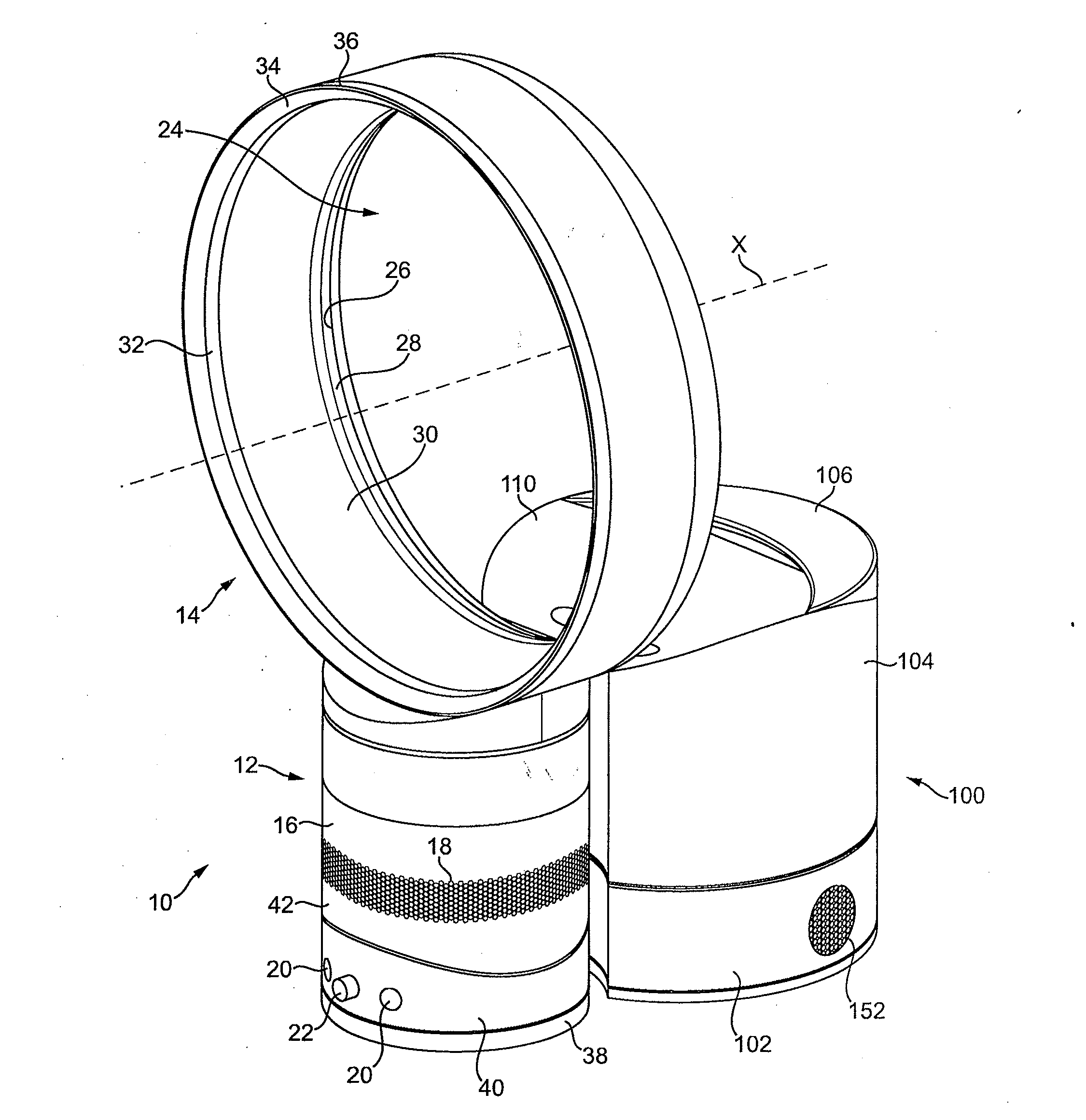
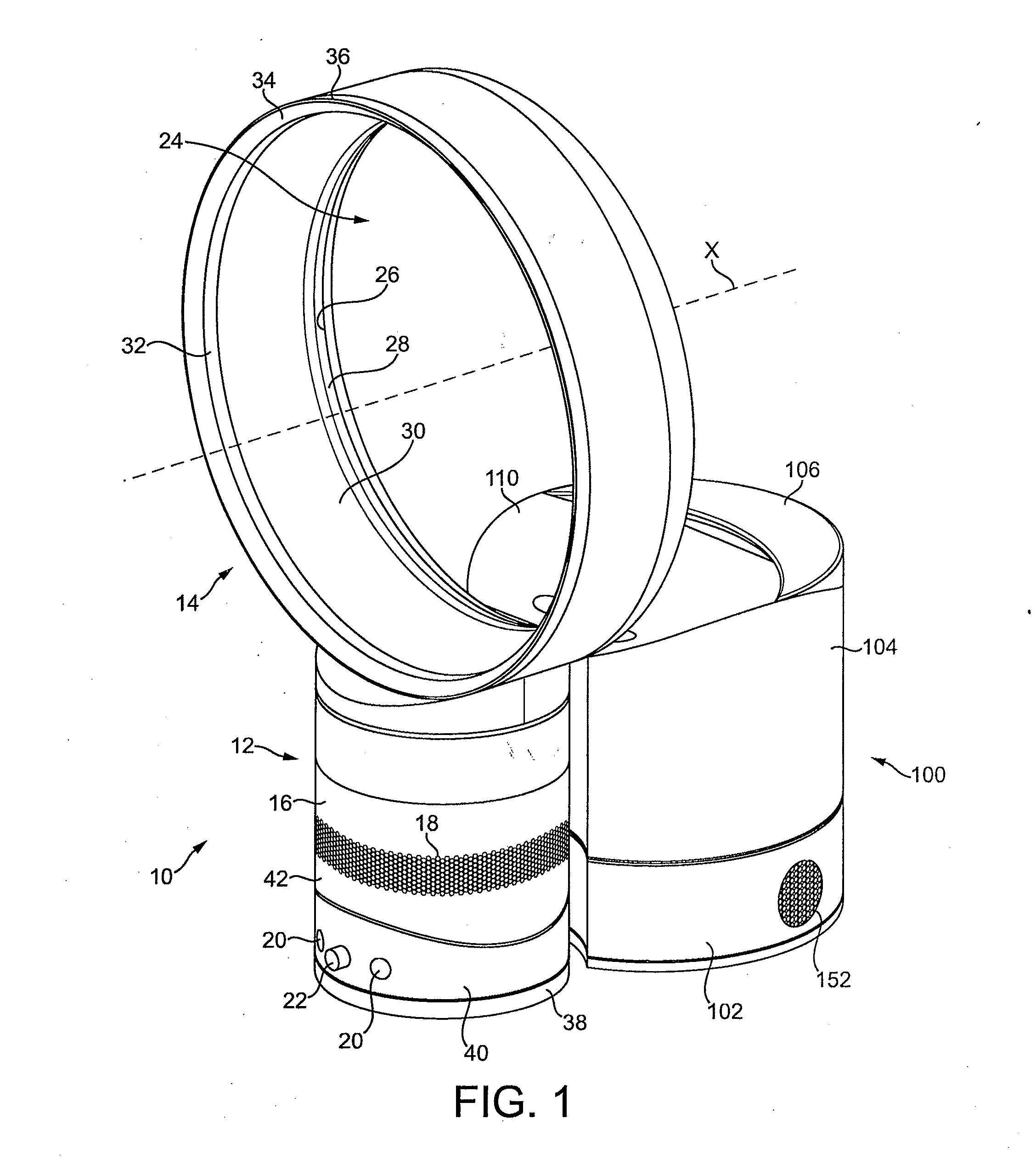
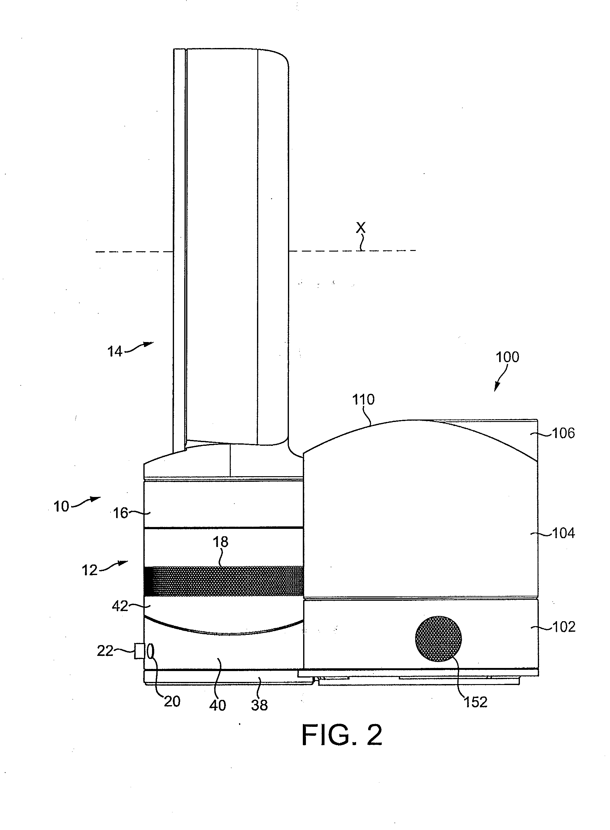
[0038]With reference first to FIGS. 1 and 2, an example of a humidifying apparatus comprises a fan assembly 10 and a humidifier 100 located behind the fan assembly 10. The fan assembly 10 is preferably in the form of a bladeless fan assembly comprising a stand 12 and a nozzle 14 mounted on and supported by the stand 12. The stand 12 comprises a substantially cylindrical outer casing 16 having a plurality of air inlets in the form of a grille 18 formed in the outer casing 16 and through which a primary air flow is drawn into the stand 12 from the external environment. The stand 12 further comprises a plurality of user-operable buttons 20 and a user-operable dial 22 for controlling the operation of the fan assembly 10. In this example the stand 12 has a height in the range from 200 to 300 mm, and the outer casing 16 has an external diameter in the range from 100 to 200 mm.

[0039]The nozzle 14 has an annular shape and defines a central opening 24. The nozzle 14 has a height in the range...


PUM

PropertyMeasurementUnit
widthaaaaaaaaaa
flow rateaaaaaaaaaa
heightaaaaaaaaaa

Abstract

Humidifying apparatus includes a humidifier for emitting moist air into an external environment, and a fan assembly for generating an air current within the external environment for conveying the emitted moist air away from the humidifier. The fan assembly includes a device for creating an air flow and a nozzle comprising an interior passage for receiving the air flow and a mouth for emitting the air flow. The humidifier is located behind nozzle, the nozzle extending about and defining an opening through which both air from outside the nozzle and the moist air emitted from the humidifier are drawn by the air flow emitted from the mouth.

Description

REFERENCE TO RELATED APPLICATIONS[0001]This application claims the priority of United Kingdom Application Nos. 0903690.6, filed 4 Mar. 2009, and 0915033.5, filed 28 Aug. 2009, the entire contents of which are incorporated herein by reference.FIELD OF THE INVENTION[0002]The present invention relates to humidifying apparatus. In a preferred embodiment, the present invention relates to humidifying apparatus comprising a fan assembly for generating an air current for dispersing moist air within a domestic environment, such as a room, office or the like.BACKGROUND OF THE INVENTION[0003]Domestic humidifying apparatus is generally in the form of a portable appliance having a casing comprising a water tank for storing a volume of water, and a fan for creating a flow of air through an air duct of the casing. The stored water is conveyed, usually under gravity, to an atomizing device for producing water droplets from the received water. This device may be in the form of high frequency vibrati...

Claims


Application Information

Patent Timeline
Patent Type & Authority Applications(United States)
IPC IPC(8): B01F3/04F04D25/08F04D29/32F04D29/52F24F1/01F24F6/00
CPCF24F1/01F24F6/14F24F13/26Y02B30/80F24F2221/28Y02B30/545F04F5/16F24F2006/125B05B17/0615F04D25/08Y02B30/54Y02B30/70
Inventor FITTON, NICHOLAS GERALDSUTTON, JOHN SCOTTGAMMACK, PETER DAVIDDYSON, JAMES
Owner DYSON TECH LTD
Why Eureka
Try Eureka