

Submachine gun target system
- Summary
- Abstract
- Description
- Claims
- Application Information
AI Technical Summary
Benefits of technology
Problems solved by technology
Method used
Image

Examples
Embodiment Construction
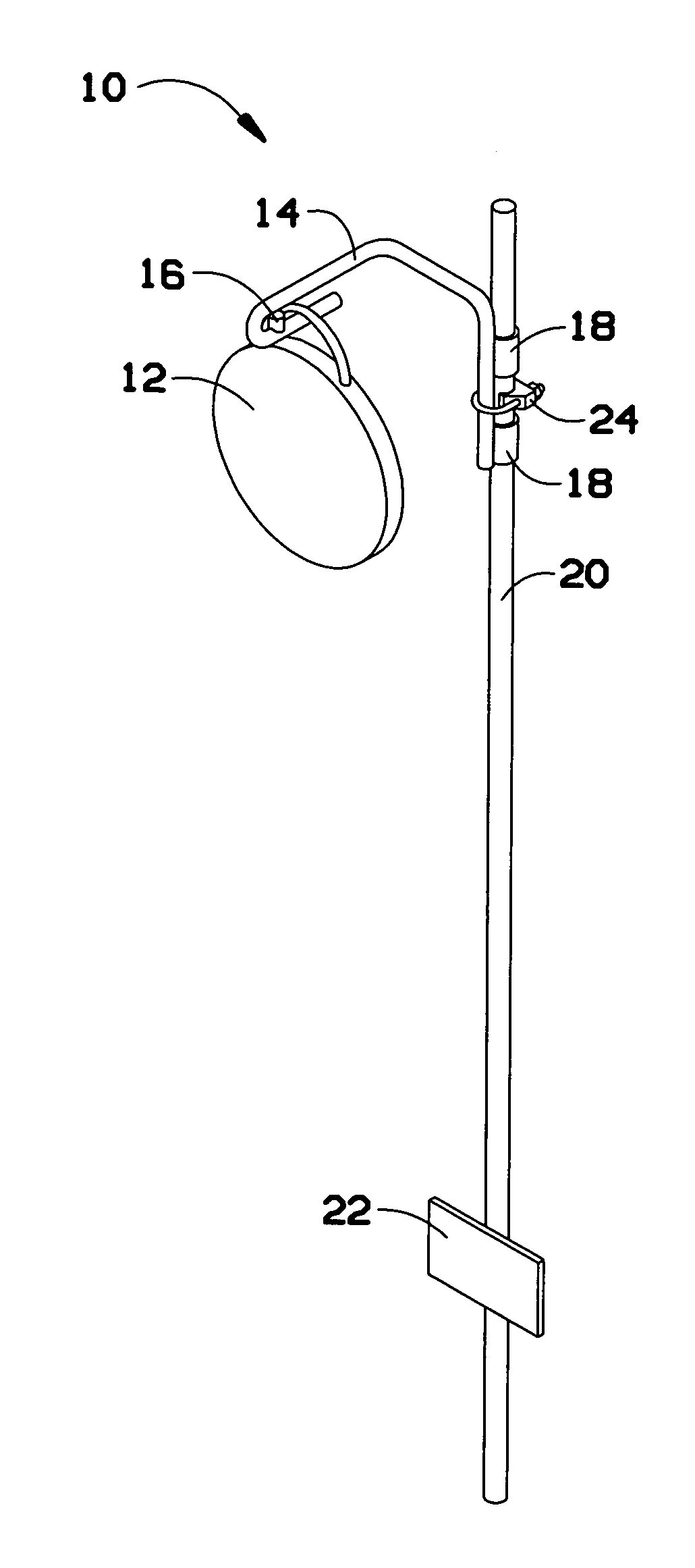
[0019]A preferred embodiment of the submachine gun target system of the present invention is shown and generally designated by the reference numeral 10.
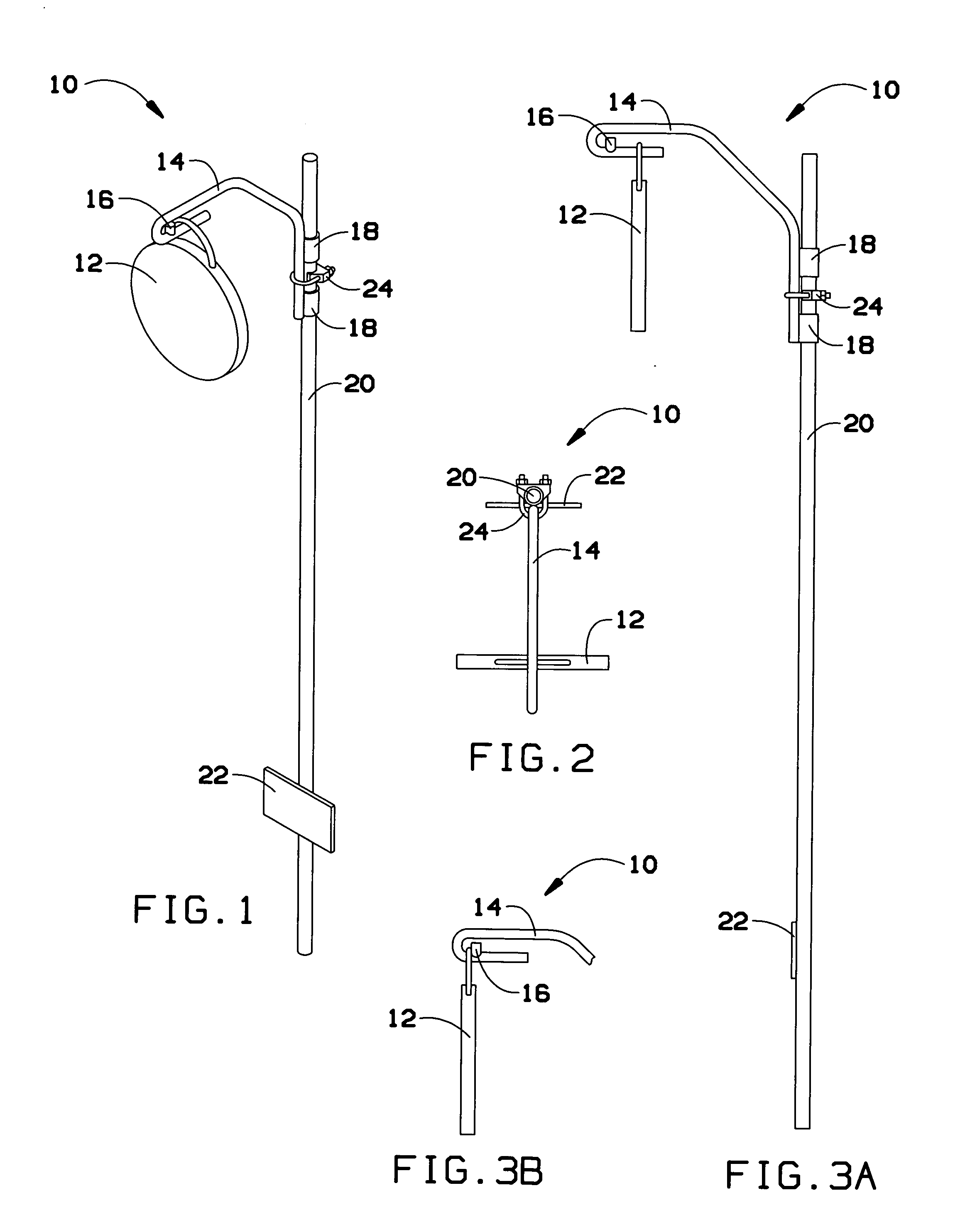
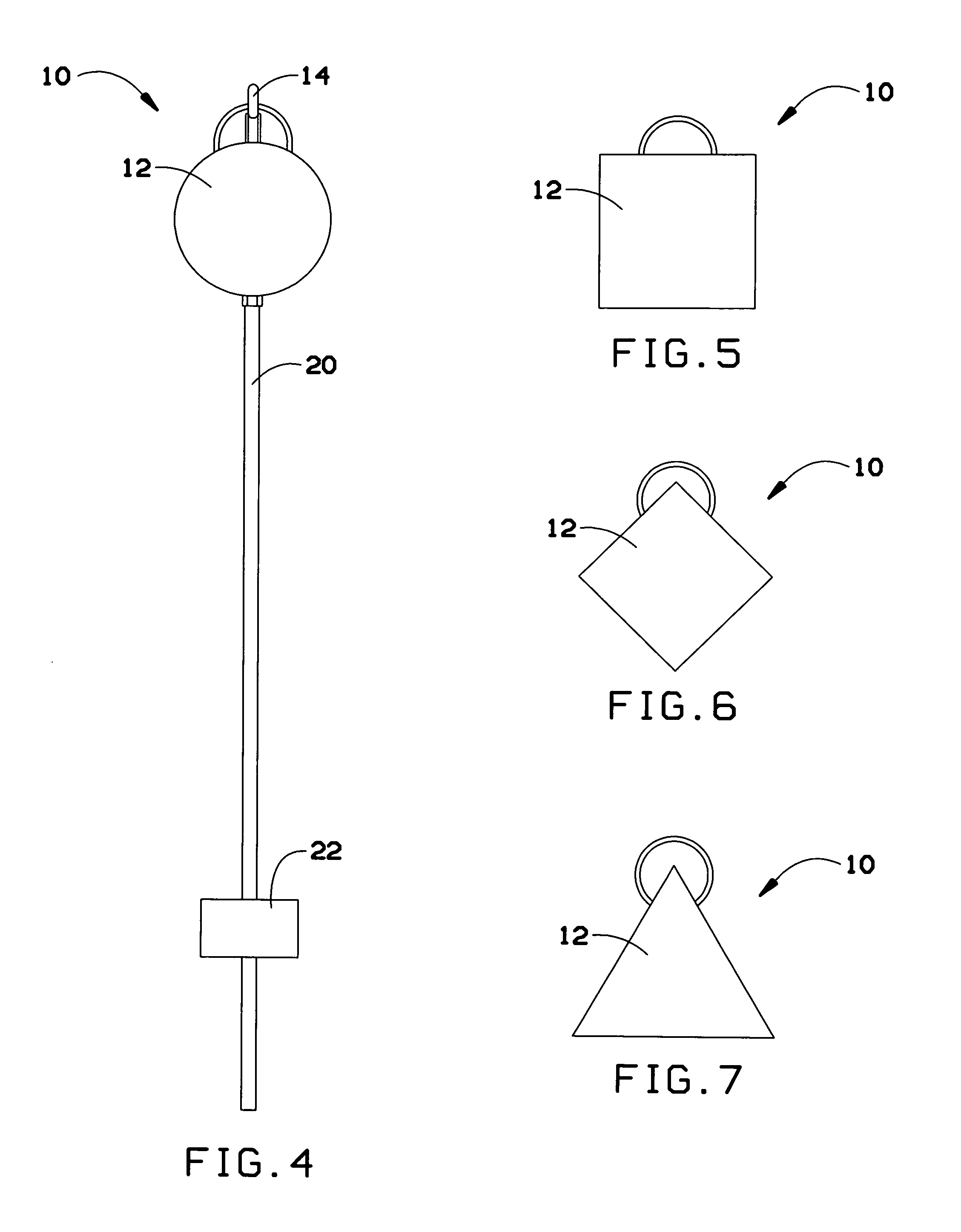
[0020]FIG. 1 illustrates improved submachine gun target system 10 of the present invention. More particularly, the target system consists of comprises a hook and post design 14, 20 that holds a hanging metal target 12. A metal round bar post 20 with a small plate 22 welded at the bottom is staked into the ground, and a hook 14 that can be adjusted for height goes over the post 20 holding a target plate 12 to face the competitive shooter.
[0021]The post 20 is a round metal bar that is ½ to ¾ inches in diameter and from 3 to 5 feet tall. The attached plate 22 is a metal plate that is 3 / 16 to 1 inch thick and 3 to 5 inches in both width and length. It is welded to the ½ to ¾ inch round bar post 5 to 8 inches from the bottom end of post so that when the post is staked into the ground, the post will not turn when a projectile hits the meta...
PUM
 Abstract
Description
Claims
Application Information