Vehicle Safety Camera System

a camera system and vehicle technology, applied in the field of vehicle safety accessories, can solve the problems of untimely report, many loss of life and property damage, and driving activity, and achieve the effects of facilitating safe sharing of the road by passenger cars, saving lives, and making the roads safer

Inactive Publication Date: 2010-09-09
WEBSTER ALLEN E
View PDF7 Cites 45 Cited by
  • Summary
  • Abstract
  • Description
  • Claims
  • Application Information

AI Technical Summary

Benefits of technology

[0010]The present invention solves the above-mentioned problems by providing an effective way to make the roads safer and encourage safe sharing of the roads by passenger cars and large trucks. The present invention aids the federal and other authorities in accident investigation of accidents involving large trucks and to generate feedback to those drivers, their companies, and the Federal Motor Carrier Safety Administration (FMCSA) or other federal authorities. This will aid in accurate statistics as well as accurate vehicle, driver, and company certification. As an additional result it will provide feedback to help make our roads safer, save lives, and minimize property damage. One aspect of the invention is a monitoring and recording feedback system of several recording video cameras mounted externally on a vehicle (typically a l

Problems solved by technology

For many years, there have been problems, esp. with large trucks but also with passenger cars and other vehicles, concerning driving activity—mainly turns and changing lanes.
When automobiles—or other smaller vehicles such as motorcycles—are traveling in a large vehicle's “blind spot,” they do not always understand the intention or simply choose to ignore the intention of the large vehicle's driver, and the large vehicle's driver cannot see them.
This creates a dangerous situation which in the past has been responsible for much loss of life and property damage.
Accident reports, because written or typed by human personal, can be inadvertently or intentionally mistyped, and so sometimes the federal authorities do not have an accurate report of the accident and events leading up to it.
These monitors may give the driver a view of what is in his blind spot at that instant in time, but this type of system creates two new problems: 1) the driver's eyes are taken off the road, and 2) the d

Method used


Image

  • Vehicle Safety Camera System
  • Vehicle Safety Camera System
  • Vehicle Safety Camera System

Examples


Embodiment Construction

[0029]The following specification describes a vehicle safety camera system. In the description, specific materials and configurations are set forth in order to provide a more complete understanding of the present invention. But it is understood by those skilled in the art that the present invention can be practiced without those specific details. In some instances, well-known elements are not described precisely so as not to obscure the invention.

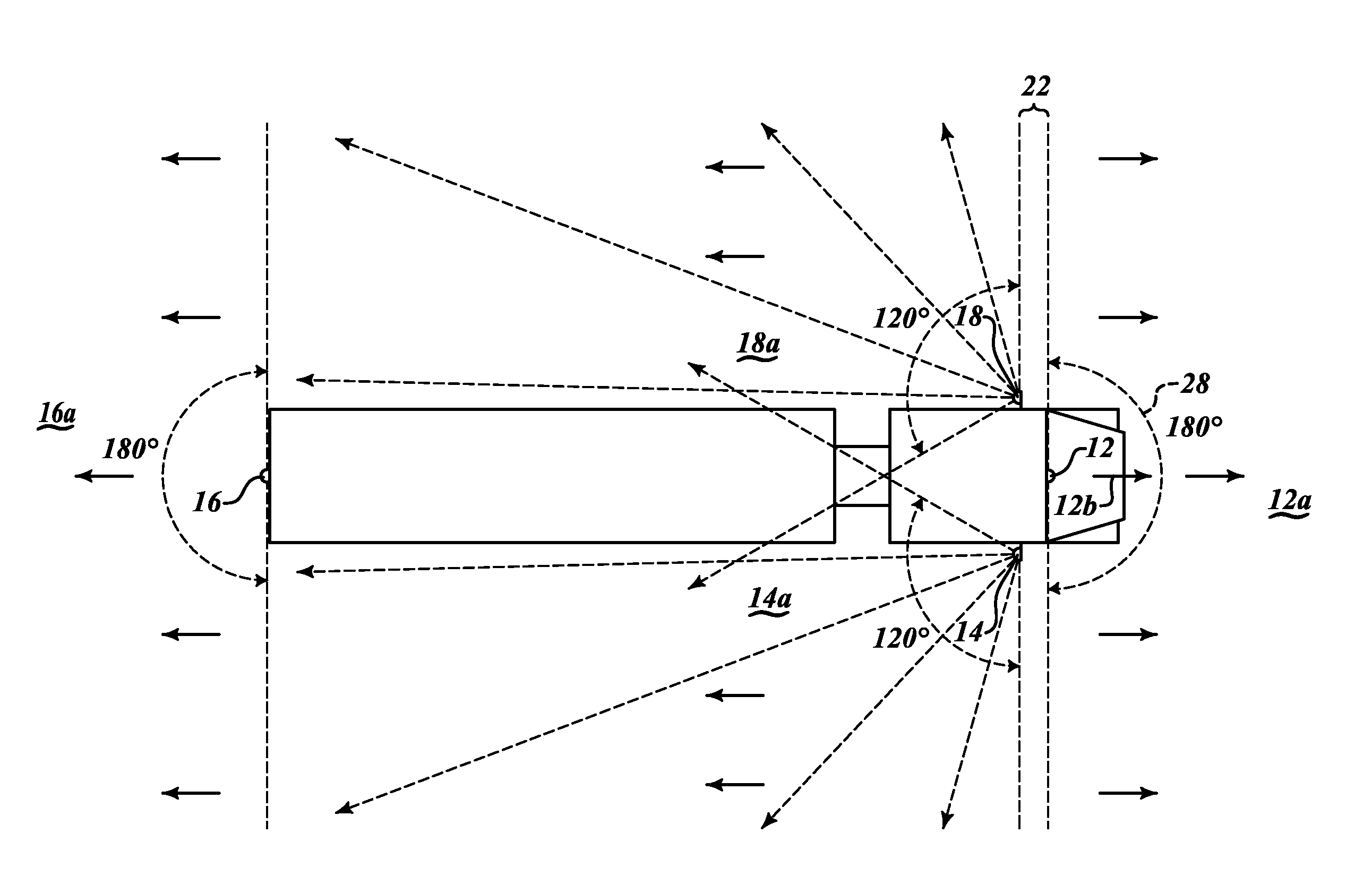
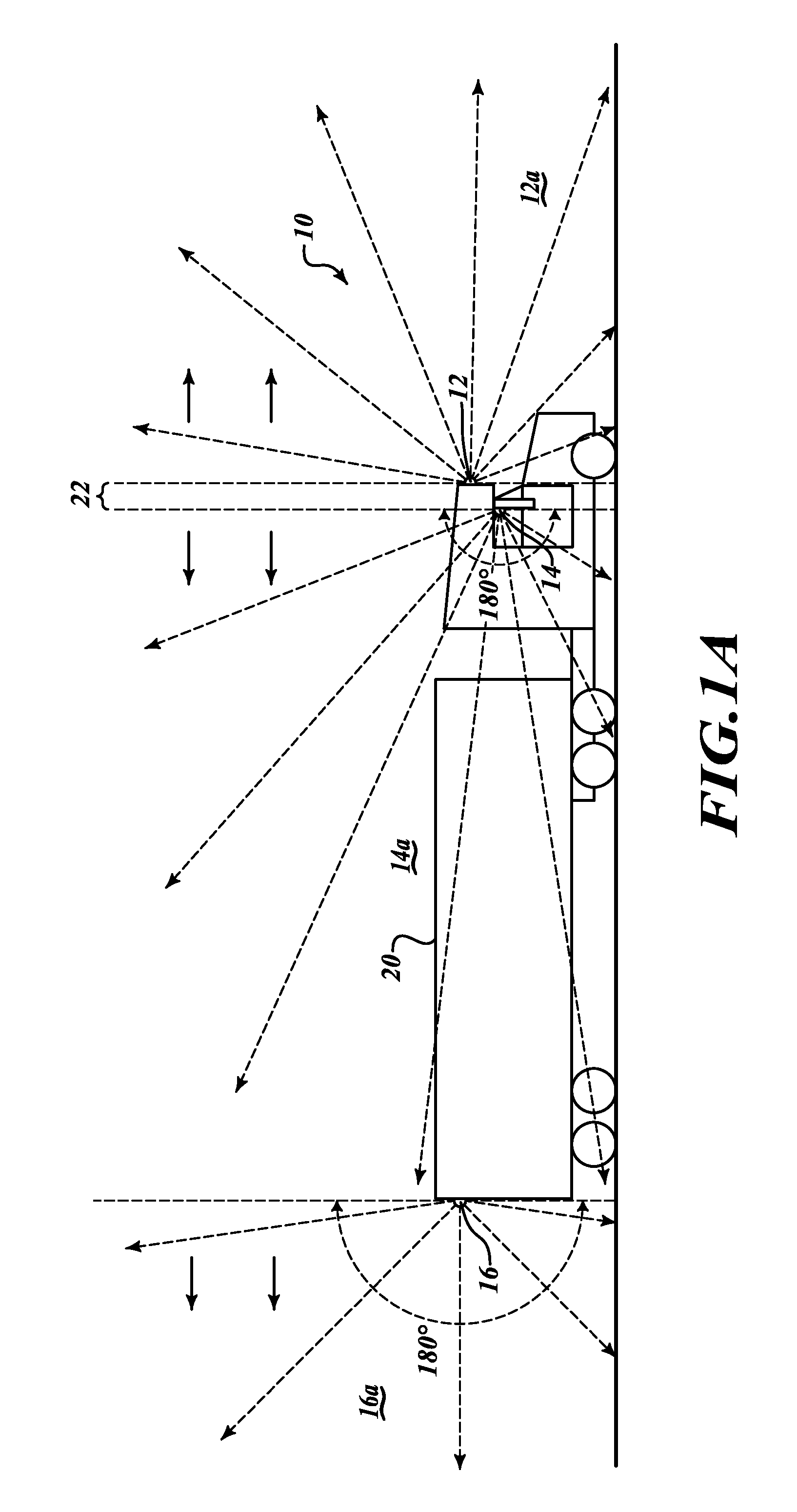
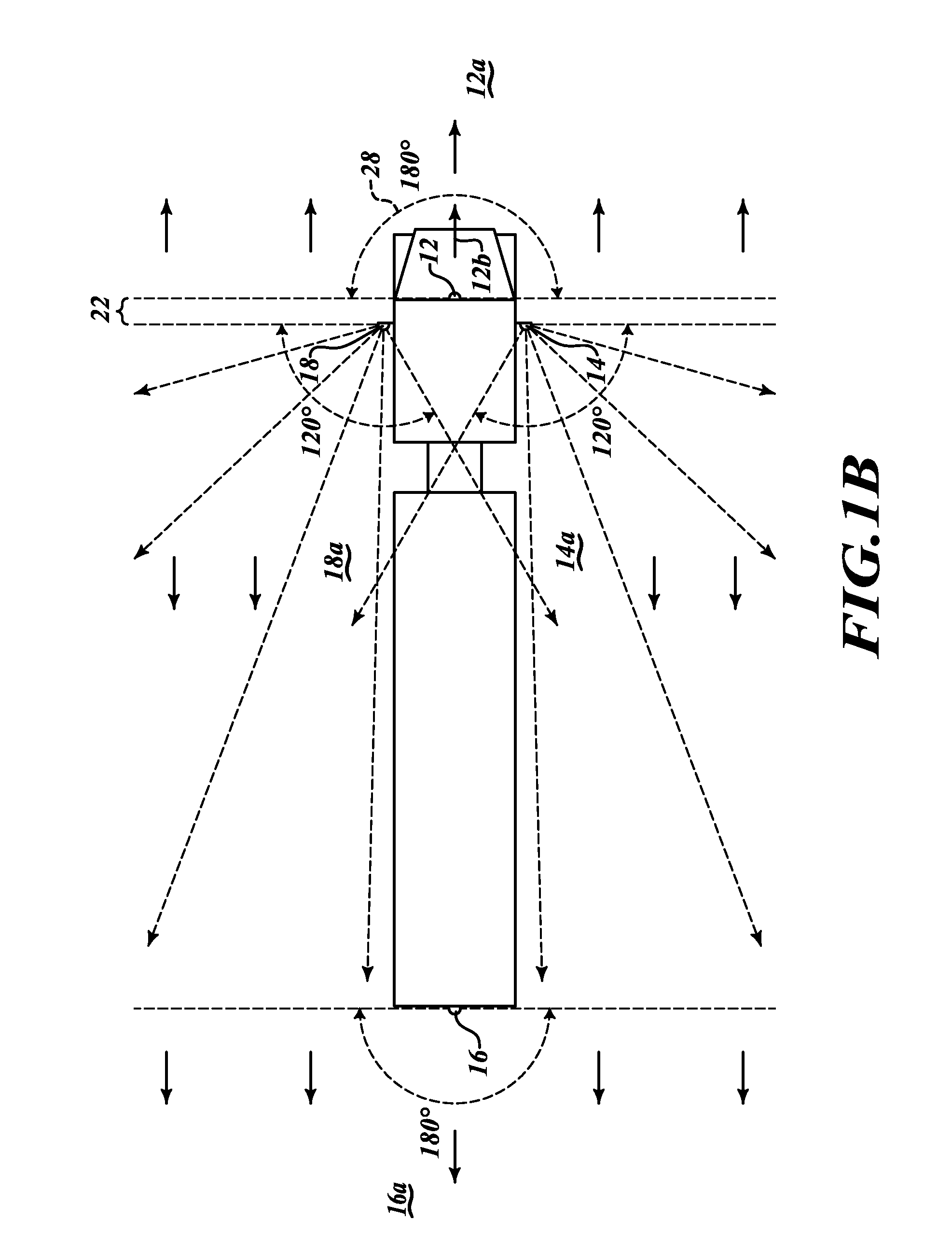
[0030]FIG. 1A shows a possible arrangement of the vehicle safety camera system, more specifically known as an external monitoring and recording feedback system 10. In this preferred embodiment of the monitoring system, there are four recording cameras 12, 14, 16, and 18 mounted respectively on the front area, right side (typically adjacent the right side mirror), rear area, and left side (typically adjacent the left side mirror and shown in FIG. 1B) of a vehicle 20 and linked wirelessly to the black box 70 (shown in FIG. 7) installed inside...


PUM


Abstract

An externally-mounted camera system for large commercial trucks. The video cameras are positioned around the outside of the vehicle and feed their video images to a control unit within a tamper-proof black box typically located within the truck's cab. The cameras are wide-angle 360 degree type cameras and only four cameras completely surrounding the truck. This system is designed to work with the Federal Motor Carrier Safety Administration and Accident Reporting regulations, standards, and protocols. The video feeds will be attached to accident reports and reviewed by the federal authorities who provide feedback in compiled statistics and enhanced safety regulations.

Description

RELATED APPLICATIONS [0001]This application is related to and claims priority under 35 U.S.C. 119(e) to U.S. provisional application Ser. No. 61 / 000,957, entitled “Blind Spot Recording Camera for Vehicles,” filed on Oct. 30, 2007, with inventor Allen Webster, which is hereby incorporated by reference in its entirety.FIELD OF THE INVENTION [0002]This invention pertains generally to vehicle safety accessories and more particularly to a system of camera devices used to record activity all around a vehicle, including in the blind spot areas.BACKGROUND OF THE FIELD [0003]For many years, there have been problems, esp. with large trucks but also with passenger cars and other vehicles, concerning driving activity—mainly turns and changing lanes. There is typically at least one area on the periphery of the vehicle where the driver cannot see even with mirrors, and this area(s) is called a “blind spot.” There actually may be several blind spot areas for any given vehicle. When automobiles—or ...

Claims


Application Information

Patent Timeline
IPC IPC(8): H04N5/225
CPCB60R11/04G07C5/0891G07C5/0866B60R2011/004
Inventor WEBSTER, ALLEN E.
Owner WEBSTER ALLEN E
Why Eureka
Try Eureka