Image forming apparatus

a technology of image forming apparatus and sensor, which is applied in the direction of electrographic process apparatus, instruments, optics, etc., can solve the problem that the output of the sensor which measures the patch often fails to have the value necessary for detecting the patch

Inactive Publication Date: 2010-09-09
FUJIFILM BUSINESS INNOVATION CORP
View PDF4 Cites 10 Cited by
  • Summary
  • Abstract
  • Description
  • Claims
  • Application Information

AI Technical Summary

Benefits of technology

[0011]According to an aspect of the invention, there is provided an image forming apparatus including: a plurality of image forming units which form toner images of different colors, respectively; an image carrier onto which the color toner images respectively formed by the image forming units are transferred, and which carries the color toner images; a first operation controlling unit which performs a first operation control of driving the image forming units and the image carrier in accordance with a printing speed that is selectively designated from a plurality of printing speeds, and transferring the color toner images formed by the image forming units to a recording medium; a second operation controlling unit which performs a second operation control of activating a position deviation correction mode where position deviations of the toner images formed by the image forming units are corrected, driving the image forming units and the image carrier, and forming image position deviation correction patterns of the colors on the image carrier, the patterns having a size and axis-to-axis distance that correspond to the currently set printing speed; a density detecting sensor which detects densities of the images formed on the image carrier; a measuring unit which binarizes a density detection output of the image position deviation correction patterns formed on the image carrier, from the density detecting sensor, and which measures intervals between color patterns of the image position deviation correction patterns, based on the binarized output; and a position deviation correction controlling unit which performs a position deviation correcting control of, when the intervals measured by the measuring unit and of the color patterns in the image position deviation correction patterns are deviated from a predetermined range, correcting position deviation of the toner images formed by the image forming units.

Problems solved by technology

When transfer timings of the image forming sections are caused to be delicately deviated from one another by a temperature rise in the apparatus, a temporal change, or the like, therefore, so-called misregistration in which only a specific color is printed while being deviated in one image occurs.
When the printing speed is high and a transfer / conveyor belt on which a patch is formed is moved at a high speed, therefore, the output of a sensor which measures the patch often fails to have a value necessary for detecting the patch.

Method used


Image

  • Image forming apparatus
  • Image forming apparatus
  • Image forming apparatus

Examples


example 1

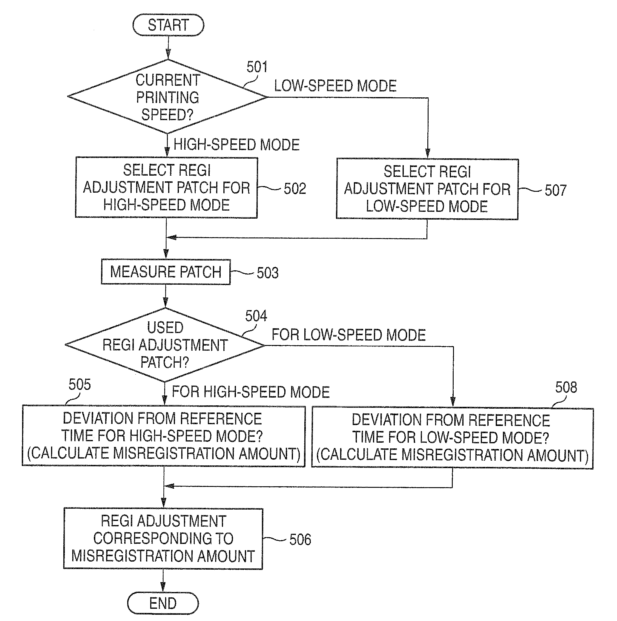
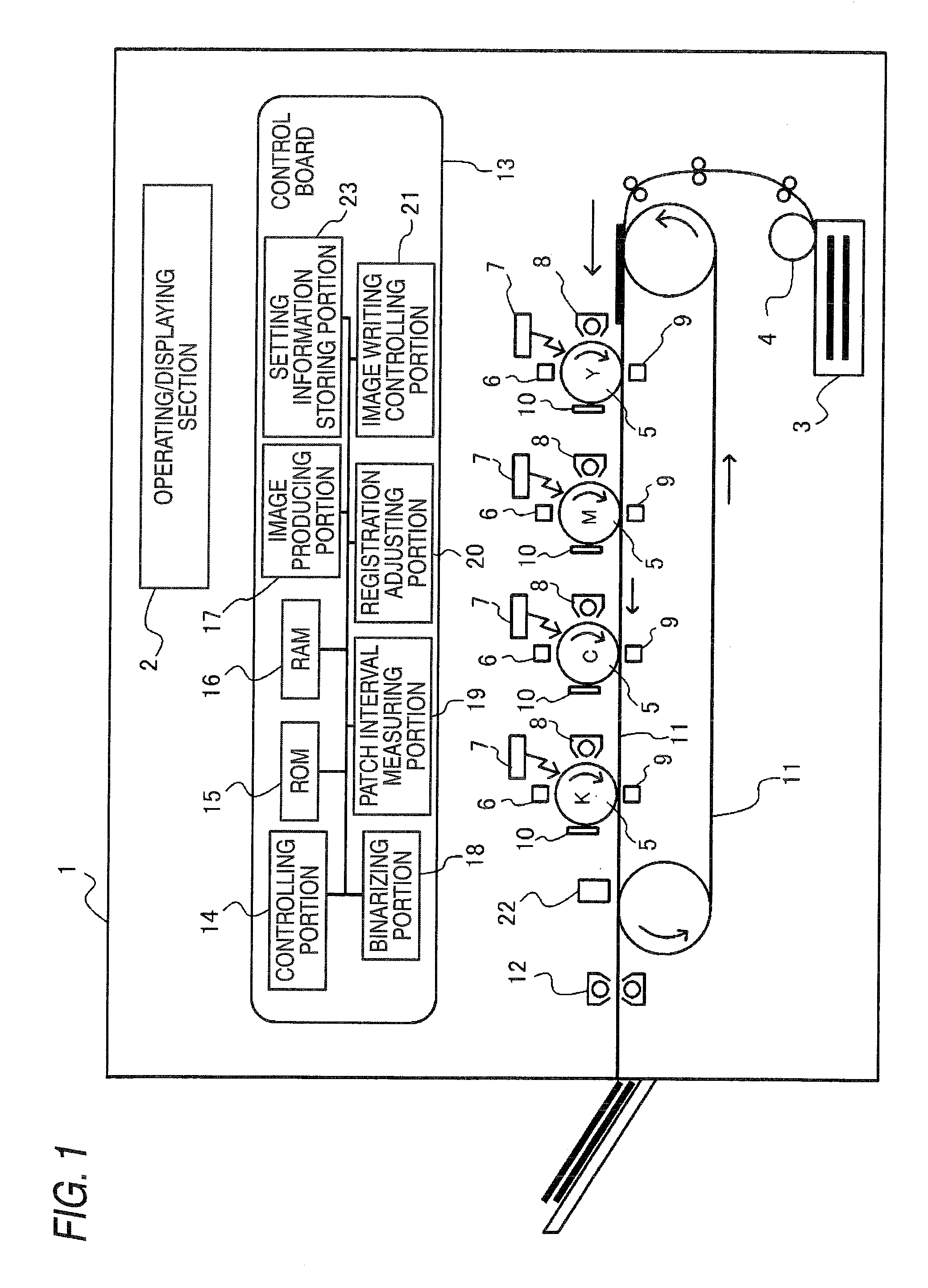
[0079]The image forming apparatus 1 in which there are regi adjustment patches for the high-speed mode where the printing speed is high, and those for the low-speed mode where the printing speed is low will be described.

[0080]The regi adjustment patches in the case where the printing speed is set to the high-speed mode (the case where the transfer / conveyor belt 11 is moved at a high speed), and those in the case where the printing speed is set to the low-speed mode (the case where the transfer / conveyor belt 11 is moved at a low speed) will be summarily described with reference to FIGS. 3A and 3B.

[0081]FIGS. 3A and 3B are diagrams showing the regi adjustment patches for the high- and low-speed modes, FIG. 3A is a diagram showing the regi adjustment patches for the high-speed mode in the case where the printing speed is set to the high-speed mode, and FIG. 3B is a diagram showing those for the low-speed mode in the case where the printing speed is set to the low-speed mode.

[0082]As sh...

example 2

[0108]The image forming apparatus 1 will be described in which, in the case where the printing speed of the image forming apparatus 1 is deemed as the moving speed of the transfer / conveyor belt 11 and the maximum moving speed of the transfer / conveyor belt 11 is indicated by V, there exist regi adjustment patches in the case where the moving speed of the transfer / conveyor belt 11 is V, those in the case where the moving speed of the transfer / conveyor belt 11 is (½)V, and those in the case where the moving speed of the transfer / conveyor belt 11 is (⅓)V, according to a change of the printing speed.

[0109]FIGS. 7A to 7C are diagrams showing regi adjustment patches in the respective printing speeds. FIG. 7A is a diagram showing the regi adjustment patches in the case where the moving speed of the transfer / conveyor belt 11 is V, FIG. 7B is a diagram showing those in the case where the moving speed of the transfer / conveyor belt 11 is (½)V, and FIG. 7C is a diagram showing those in the case ...


PUM


Abstract

An image forming apparatus includes: a plurality of image forming units as defined herein; an image carrier as defined herein; a first operation controlling unit as defined herein; a second operation controlling unit as defined herein; a density detecting sensor that detects densities of the images formed on the image carrier; a measuring unit that binarizes a density detection output of the image position deviation correction patterns formed on the image carrier, from the density detecting sensor, and that measures intervals between color patterns of the image position deviation correction patterns, based on the binarized output; and a position deviation correction controlling unit that performs a position deviation correcting control of, when the intervals measured by the measuring unit and of the color patterns in the image position deviation correction patterns are deviated from a predetermined range, correcting position deviation of the toner images formed by the image forming units.

Description

CROSS-REFERENCE TO RELATED APPLICATIONS [0001]This application is based on and claims priority under 35 USC 119 from Japanese Patent Application No. 2009-050650 filed on Mar. 4, 2009.BACKGROUND [0002]1. Technical Field[0003]The present invention relates to an image forming apparatus.[0004]2. Related Art[0005]As an image forming apparatus which performs color printing, there is a tandem type apparatus in which image forming sections (photosensitive members, exposing devices, and the like) that transfer toner images of colors (Y (yellow), M (magenta), C (cyan), and K (black)) to a sheet are provided respectively for the colors.[0006]In the tandem type image forming apparatus, the respective image forming sections perform a printing operation on one sheet to form a color image configured by toner images of the four colors.[0007]When transfer timings of the image forming sections are caused to be delicately deviated from one another by a temperature rise in the apparatus, a temporal cha...

Claims


Application Information

Patent Timeline
Patent Type & Authority Applications(United States)
IPC IPC(8): G03G15/01
CPCG03G2215/00059G03G2215/0141G03G15/5058G03G15/0194G03G2215/0161
Inventor OSAWA, FUJIOMISUMI, HAJIMEKAGEYAMA, HIDEOKUBO, TAKASHISHIOI, MITSUNORISAITOU, KANOUTAKAGAKI, SUSUMUTSUTEHIRA, TADAKAZUSATO, YUJI
Owner FUJIFILM BUSINESS INNOVATION CORP
Why Eureka
Try Eureka