Surface cleaning apparatus

a surface cleaning and hose technology, applied in the direction of suction cleaners, cleaning equipment, suction nozzles, etc., can solve the problems of reducing the chance that the slack hose portion may become kinked, creating potential tripping hazards for users, and increasing the separation distance. , to achieve the effect of reducing the stress and strain experienced by users, facilitating surface cleaning ahead, and increasing separation distan

Active Publication Date: 2010-09-16
OMACHRON INTPROP
View PDF19 Cites 69 Cited by
  • Summary
  • Abstract
  • Description
  • Claims
  • Application Information

AI Technical Summary

Benefits of technology

[0008]According to another broad aspect, a surface cleaning apparatus, such as an upright vacuum cleaner is provided wherein an air flow path includes two or more sequentially positioned flexible hoses. The upright vacuum cleaner may have a support structure pivotally connected to a surface cleaning head. The vacuum cleaner may also include a surface cleaning unit that is removably mounted on the support structure. The dirty air inlet of the surface cleaning head is connected in fluid communication with the clean air outlet of the surface cleaning unit by an air conduit. The air conduit may include two flexible conduits or hoses that are positioned sequentially (one is upstream of the other). In use, a user may operate the surface cleaning apparatus with the surface cleaning unit attached to the support structure. Optionally, the user may detach the surface cleaning unit from the support structure and move the support structure and surface cleaning head independently from the surface cleaning unit while maintaining the operable fluid connection via the two flexible hoses. The flexible hoses may also be extensible to increase the separation distance between surface cleaning unit and the support structure.
[0009]According to another broad aspect, an upright vacuum cleaner is provided having a support structure pivotally connected to a surface cleaning head wherein a flexible hose extends through the pivot member. For example support structure may include a handle portion that is gripped by the user during use. Pivotally connecting the support structure to the surface cleaning head allows the user to easily maneuver the surface cleaning ahead across the surface to be cleaned. The pivotal connection between the surface cleaning head and the support structure may also allow a user to guide the surface cleaning head around obstacles, such as table legs. In addition, the pivotal connection allows the angle and position of the support structure to be changed while the surface cleaning head remains in contact with the floor. This enables users of different heights to comfortably use the vacuum cleaner, and it may reduce the stress and strain experienced by the user when vacuuming. Accordingly, the pivot mount may include mounting arms and may define a passageway or conduit through which a flexible hose or conduit can extend. The surface cleaning apparatus may also include a surface cleaning unit that is removably mounted on the support structure. The dirty air inlet of the surface cleaning head is connected in fluid communication with the clean air outlet of the surface cleaning unit by an air conduit. The air conduit may optionally include two flexible conduits or hoses. In such a case, the upstream flexible hose may pass through the conduit in the pivot mount and the pivot mount may provide a conduit through which the upstream hose and be connected to the downstream hose. Accordingly, part or all of a flexible hose may be stored in or on a surface cleaning head.
[0010]When cleaning a room, the user may detach the surface cleaning unit from the support structure and move the support structure and surface cleaning head independently from the surface cleaning unit while maintaining the operable fluid connection via the flexible hoses. This may further reduce the stress and strain experienced by the user when vacuuming. To increase the user's range of movement, one or both of the flexible hoses connecting the surface cleaning unit to the surface cleaning head may be stretchable, and preferably resiliently stretchable so that the hose will return to its unstretched length when released. When not stretched, portions of the flexible hoses may be stored in the surface cleaning head, the support structure or both. The increased length of the hoses as a result of their extensibility may reduce the need for the user to add separate extension hoses or tools to the vacuum cleaner in use, which may reduce the time required to vacuum a room. The resilient nature of the flexible hoses can also keep the hoses under tension when not in use. That is, the connection points at the end of one or more of the flexible hoses may be separated by a path length that is longer than the unstretched length of the hose. Keeping the hoses under tension when not in use may reduce the chances of the hoses becoming tangled and may reduce the chances that slack hose portions may become kinked or create potential tripping hazards for the user.
[0011]In another aspect, a hose is mounted to the surface cleaning head under tension. Accordingly, the air flow path comprises a flexible conduit wherein a portion of the flexible conduit is connected to the surface cleaning head at a location forward of a pivot axle for a support structure and another portion is connected to at least one of the support structure and a pivot mount for the support structure. This configuration applies a downward force to the front of the surface cleaning head, to assist in keeping the front of a surface cleaning head on a floor.

Problems solved by technology

While cleaning heads have been considered to have uses, typically, commercialized domestic surfacing cleaning apparatus, and in particular vacuum cleaners for household use, have not employed such cleaning heads.
Keeping the hoses under tension when not in use may reduce the chances of the hoses becoming tangled and may reduce the chances that slack hose portions may become kinked or create potential tripping hazards for the user.

Method used


Image

  • Surface cleaning apparatus
  • Surface cleaning apparatus
  • Surface cleaning apparatus

Examples


Embodiment Construction

[0119]Various apparatuses or methods will be described below to provide an example of each claimed invention. No example described below limits any claimed invention and any claimed invention may cover processes or apparatuses that are not described below. The claimed inventions are not limited to apparatuses or processes having all of the features of any one apparatus or process described below or to features common to multiple or all of the apparatuses described below. It is possible that an apparatus or process described below is not an embodiment of any claimed invention. It will be appreciated that each of the features may be used individually or in combination with any one or more other feature.

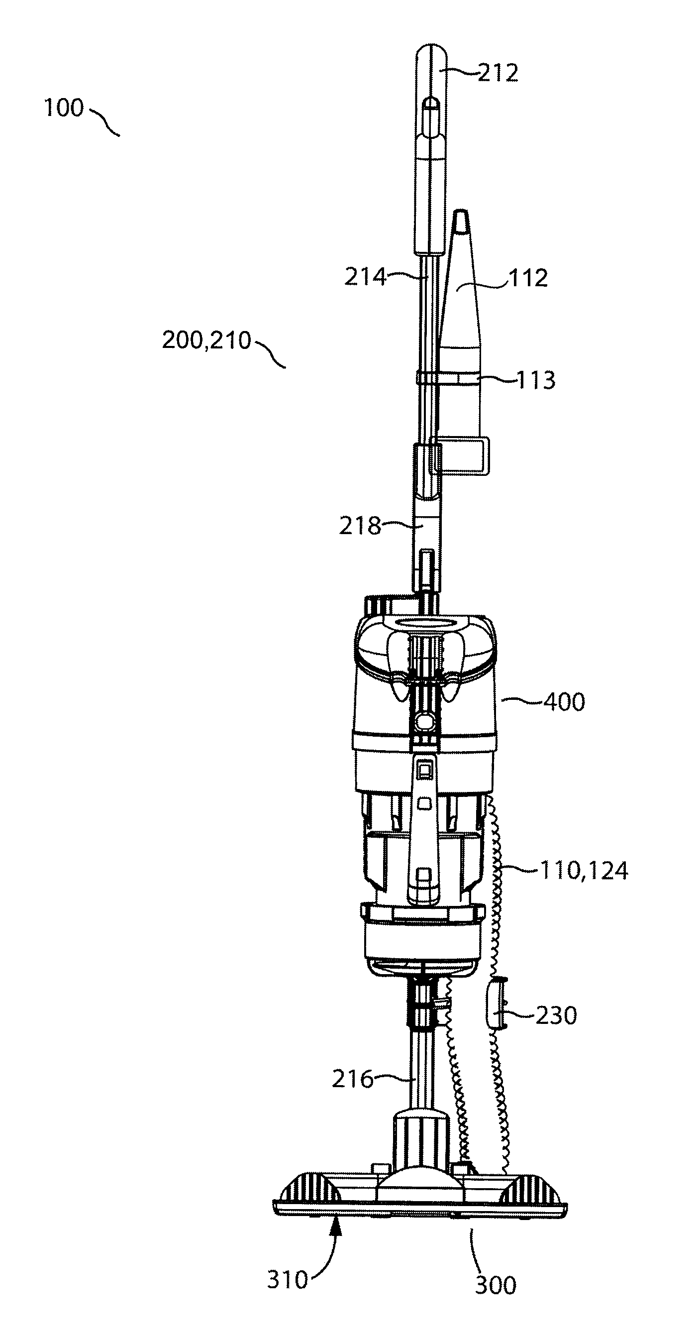
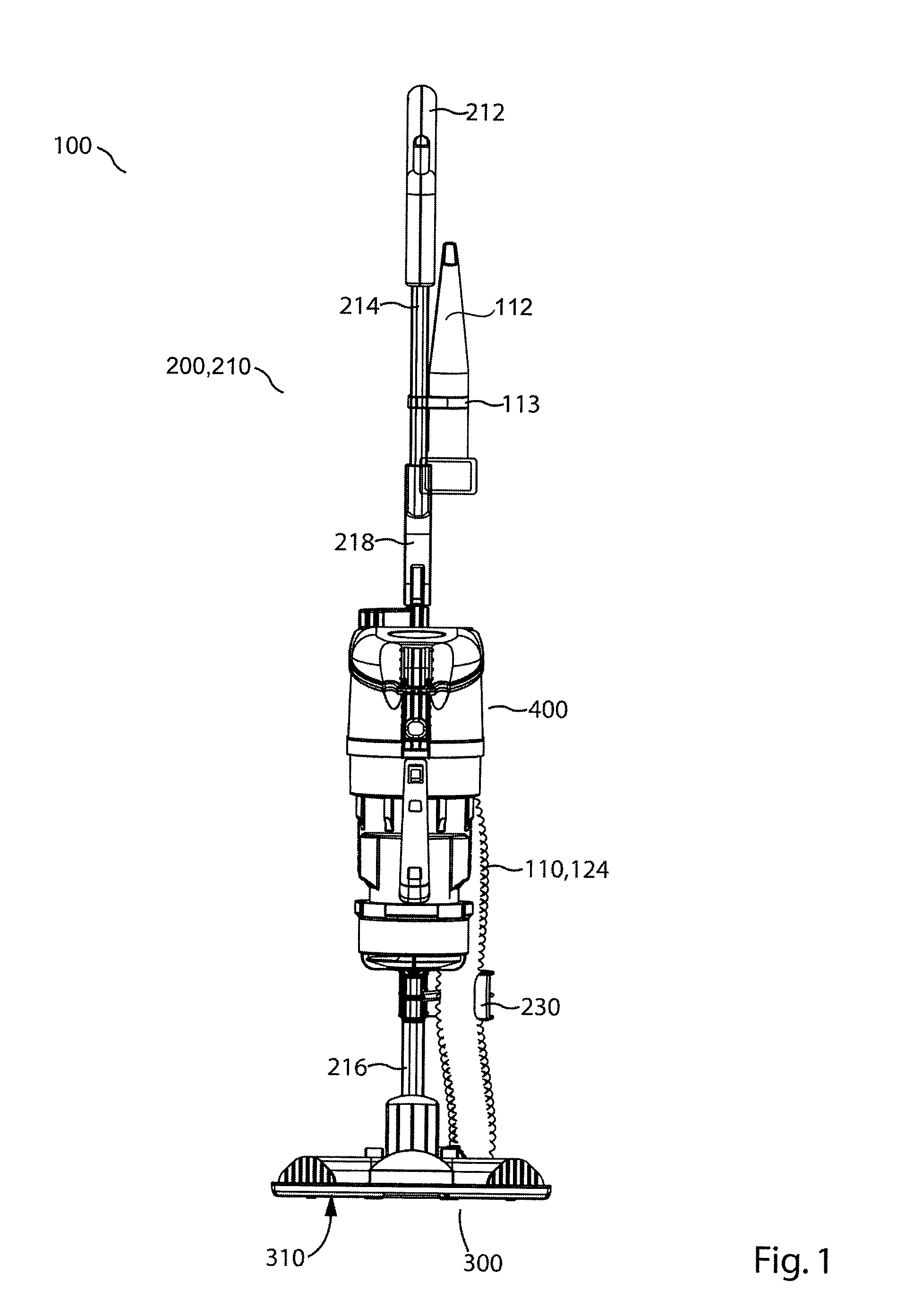
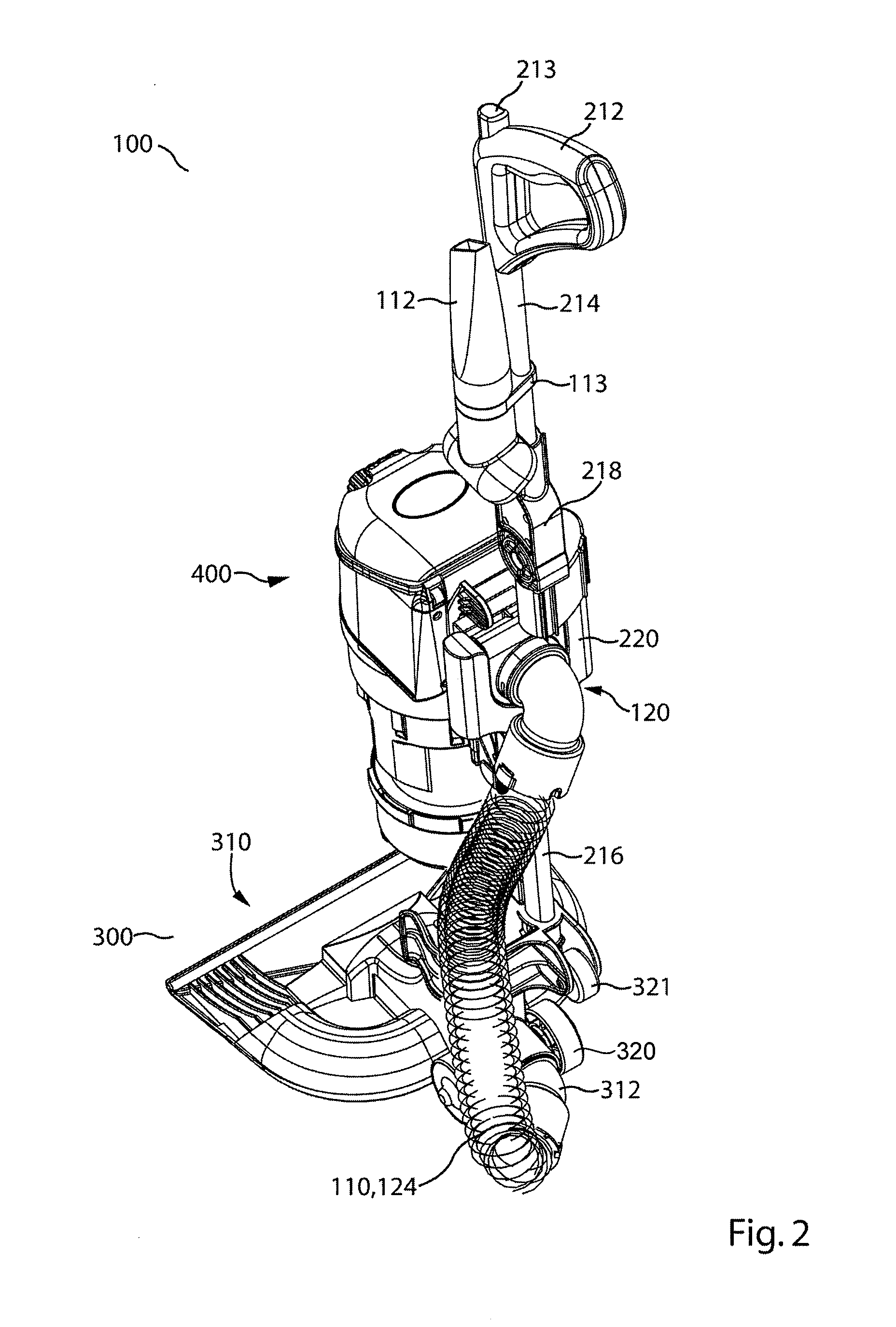
[0120]FIGS. 1-5 exemplify one example of an upright vacuum cleaner having a removably mounted portable surface cleaning apparatus, optionally a hand vacuum cleaner, wherein the portable surface cleaning apparatus has a nozzle having an open sided air flow chamber. It will be appreciated...


PUM


Abstract

Various uses and constructions for an open sided nozzle for a surface cleaning apparatus are provided. Alternate constructions for a surface cleaning head are also provided.

Description

CROSS REFERENCE TO RELATED APPLICATIONS[0001]This application claims the benefit of the filing date of Canadian Patent Application. No. 2658981, filed Mar. 13, 2009 entitled SURFACE CLEANING APPARATUS.FIELD[0002]The specification relates to surface cleaning apparatus. In one embodiment, the specification relates to a surface cleaning apparatus having a cleaning nozzle wherein the cleaning nozzle comprises an open sides air flow chamber and removably receives a attachment member. In other preferred embodiments, the specification relates to alternate constructions for a surface cleaning head.INTRODUCTION[0003]The following is not an admission that anything discussed below is prior art or part of the common general knowledge of persons skilled in the art.[0004]Cleaning apparatus that use a cleaning head having an open bottom are known. See for example U.S. Pat. No. 4,395,794; U.S. Pat. No. 5,839,157; U.S. Pat. No. 5,208,941 and U.S. Pat. No. 5,768,744. While cleaning heads have been co...

Claims


Application Information

Patent Timeline
Patent Type & Authority Applications(United States)
IPC IPC(8): A47L9/02
CPCA47L5/24A47L5/28A47L9/242A47L9/02A47L5/32
Inventor CONRAD, WAYNE ERNEST
Owner OMACHRON INTPROP
Why Eureka
Try Eureka