Unitary Electro Magnetic Coil Launch Tube

a technology of electro magnetic coils and launch tubes, which is applied in the field of missile launchers, can solve the problems of reducing the efficiency reducing the minimum separation between propulsion and separation distance, and limited ability of prior-art electromagnetic launchers, so as to reduce the minimum separation, facilitate assembly, and the effect of sufficient velocity for fligh

Active Publication Date: 2008-01-10
LOCKHEED MARTIN CORP
View PDF13 Cites 15 Cited by
  • Summary
  • Abstract
  • Description
  • Claims
  • Application Information

AI Technical Summary

Benefits of technology

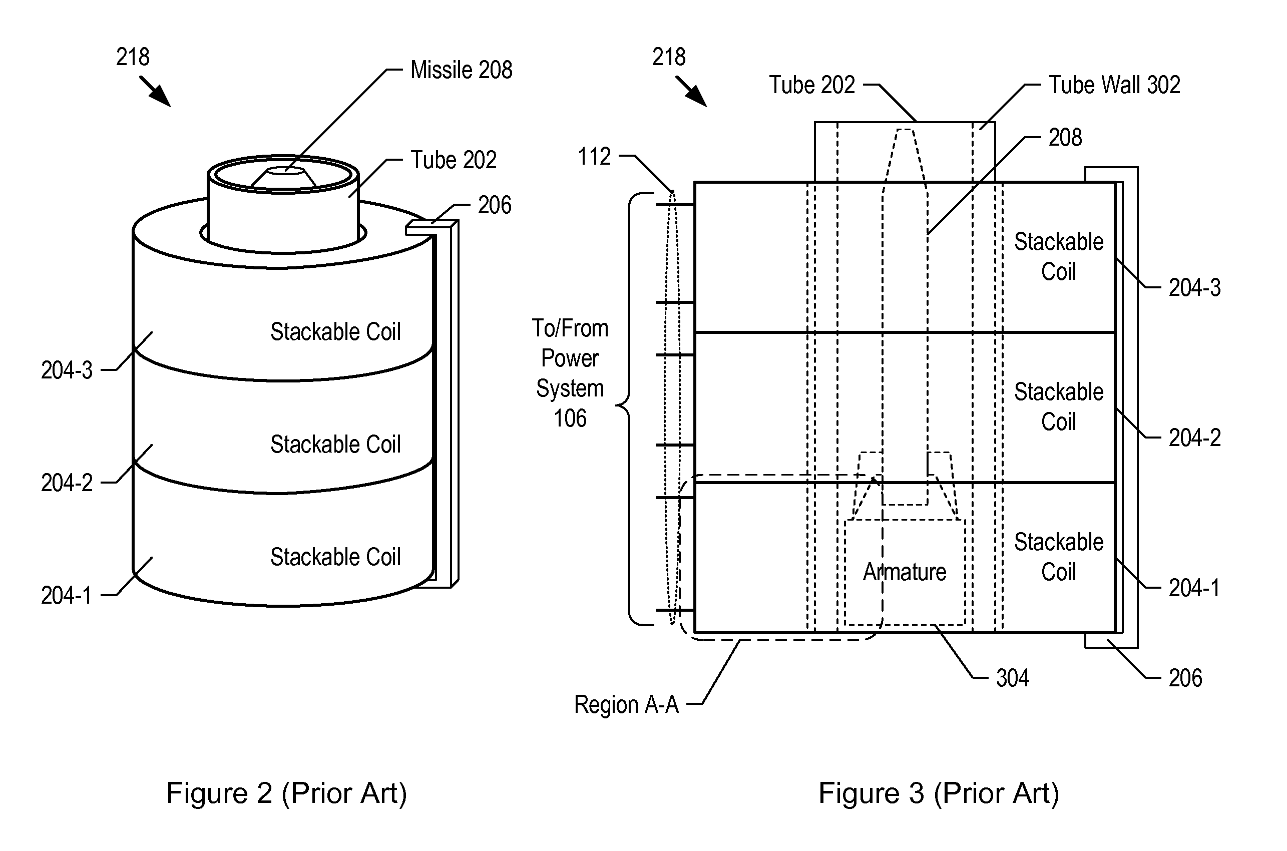
[0010]Embodiments of the present invention, like the prior art, use a plurality of propulsion coils arrayed along the length of a tube to eject a missile from the tube with sufficient velocity for flight. In some prior art electromagnetic launchers, the propulsion coils are equally-sized, stackable coils that each act as an independent unit during launch. As a result, these prior-art electromagnetic launchers are limited in their ability to: 1) vary the dimensional properties of their propulsion coils, and 2) reduce the minimum separation between the propulsion coils and an armature that propels the missile within the tube. In addition, the minimum separation between the propulsion coils and the armature in prior-art electromagnetic launchers includes extra space, which is required to facilitate their assembly. The increased separation distance reduces the efficiency of prior-art electromagnetic launchers.
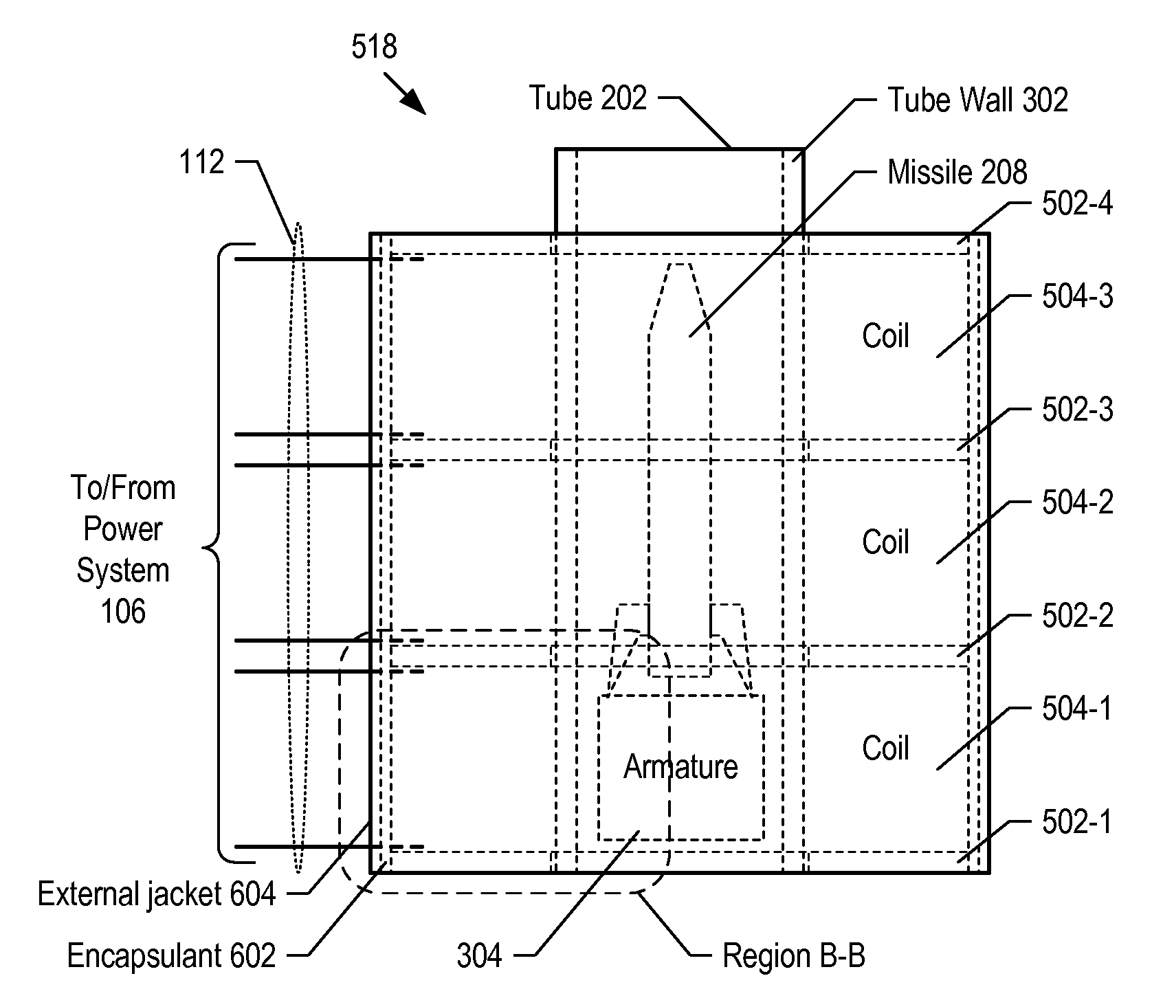
[0011]In contrast to the prior art, the present invention comprises propulsion coils that are formed directly onto the outer surface of the tube. As a result, embodiments of missile launchers in accordance with the present invention can have readily varied coil sizes, coil diameters, coil spacings, and coil wire sizes, as a function of the tube size. In addition, embodiments in accordance with the present invention can have a smaller minimum spacing between the propulsion coils and the armature.
[0012]Embodiments of the present invention derive any one or more of the following advantages over the prior art:
[0017]5) increased flexibility for use with different missile types; and
[0019]Like prior-art electromagnetic missile launchers, embodiments of the present invention eject a missile from a tube by accelerating an armature. The armature is accelerated by a force that arises due to mutual inductance between the armature and a plurality of propulsion coils that carry electric current. The flow of electric current in each propulsion coil is controlled and sequenced by a power system that is electrically-connected to the propulsion coils. But the efficiency with which the propulsion coils of launchers disclosed herein propel the armature is improved over prior-art electromagnetic missile launchers. A reason for this is that the minimum separation between the propulsion coils and the armature of the present launcher is less than for prior-art launchers.

Problems solved by technology

As a result, these prior-art electromagnetic launchers are limited in their ability to: 1) vary the dimensional properties of their propulsion coils, and 2) reduce the minimum separation between the propulsion coils and an armature that propels the missile within the tube.
In addition, the minimum separation between the propulsion coils and the armature in prior-art electromagnetic launchers includes extra space, which is required to facilitate their assembly.
The increased separation distance reduces the efficiency of prior-art electromagnetic launchers.

Method used


Image

  • Unitary Electro Magnetic Coil Launch Tube
  • Unitary Electro Magnetic Coil Launch Tube
  • Unitary Electro Magnetic Coil Launch Tube

Examples


Embodiment Construction

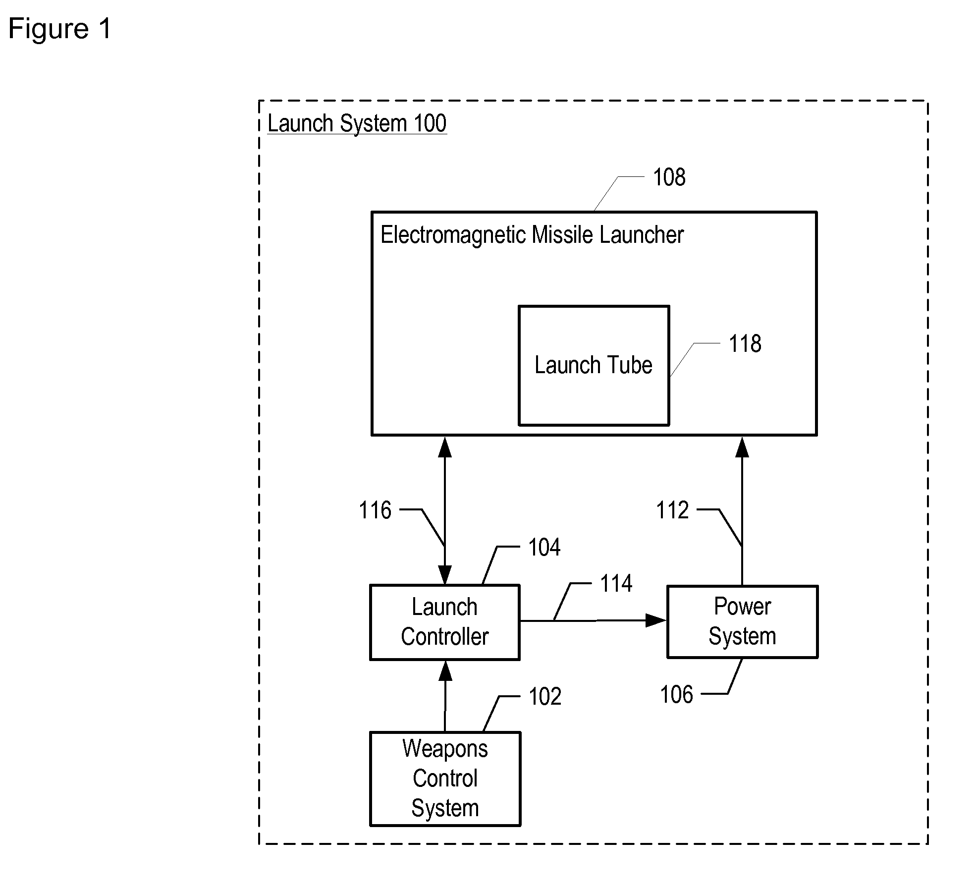
[0034]FIG. 1 depicts a schematic of the salient components of a launch system according to an illustrative embodiment of the present invention. Launch system 100 comprises electromagnetic missile launcher 108, weapons control system 102, launch controller 104, power system 106, propulsion current bus 112, signal line 114, and data bus 116. Launch system 100 is described in U.S. patent application Ser. No. 10 / 899,234, filed Sep. 26, 2004, which is incorporated by reference herein.

[0035]Electromagnetic missile launcher 108 (hereinafter “launcher 108”) is a system that has the capability to house and expel a conventional missile upon command. A conventional missile typically comprises an explosive warhead and a chemical-propellant engine. Launcher 108 comprises launch tube 118. Launcher 108 expels a missile from launch tube 118 using an electromagnetic catapult and without the aid of the missile's chemical-propulsion engine. This is advantageous because it enables the missile to clear ...


PUM


Abstract

An electromagnetic missile launcher is disclosed that provides greater flexibility for use with a variety of missile types and also provides potentially higher performance and efficiency as compared to prior-art electromagnetic missile launchers.

Description

FIELD OF THE INVENTION[0001]The present invention relates to missilery in general, and, more particularly, to missile launchers.BACKGROUND OF THE INVENTION[0002]During launch of a missile that contains a chemical booster, a thrust-providing plume of exhaust gas is generated. The exhaust gas is extremely hot (in excess of 5000° F.) and very erosive due to the presence of metallic particulates. Booster-assisted launch, which is typically referred to as “hot launch,” has a number of drawbacks, including:[0003]heating of the launch platform, which creates a readily-identifiable thermal signature;[0004]obscuring the visibility and / or temporarily blinding missile-launch personnel;[0005]impairing radar systems in the vicinity of the launch platform due to the presence of the metallic particulates in the missile exhaust; and[0006]the difficulty of adequately venting the exhaust gas from relatively larger missiles, which, in comparison with smaller missiles, is relatively hotter and more vol...

Claims


Application Information

Patent Timeline
Patent Type & Authority Applications(United States)
IPC IPC(8): F41F1/00F41B6/00
CPCF41B6/003
Inventor GAIGLER, RANDY L.ALBERDING, MARK R.BASAK, LESZEK STANISLAW
Owner LOCKHEED MARTIN CORP
Why Eureka
Try Eureka