Projection screen and ultra-short-focus projection system having projection screen

A projection screen, ultra-short-focus technology, applied in the field of projection display, can solve the problems of low beam spread and affect the quality of image viewing, and achieve the effect of improving image quality and suppressing speckle

Active Publication Date: 2016-11-16
QINGDAO HISENSE LASER DISPLAY CO LTD
View PDF8 Cites 15 Cited by
  • Summary
  • Abstract
  • Description
  • Claims
  • Application Information

AI Technical Summary

Problems solved by technology

[0004] Because the scattering layer 102 includes a lot of tiny scattering particles, different light rays (i.e. light beams) reflected back by the reflective layer 104 go through different route lengths after being scattered by the scattering particles of the scattering layer 102, but because the scattering layer 102 is in phase with the lens layer 103 Adjacent to the setting, the diffusion degree of the beam is not high, and the scattering particles passing by a

Method used


Image

  • Projection screen and ultra-short-focus projection system having projection screen
  • Projection screen and ultra-short-focus projection system having projection screen
  • Projection screen and ultra-short-focus projection system having projection screen

Examples


Embodiment 1

[0021] Based on the problems discovered by the inventors, this application proposes a projection screen that can significantly reduce speckle, as follows:

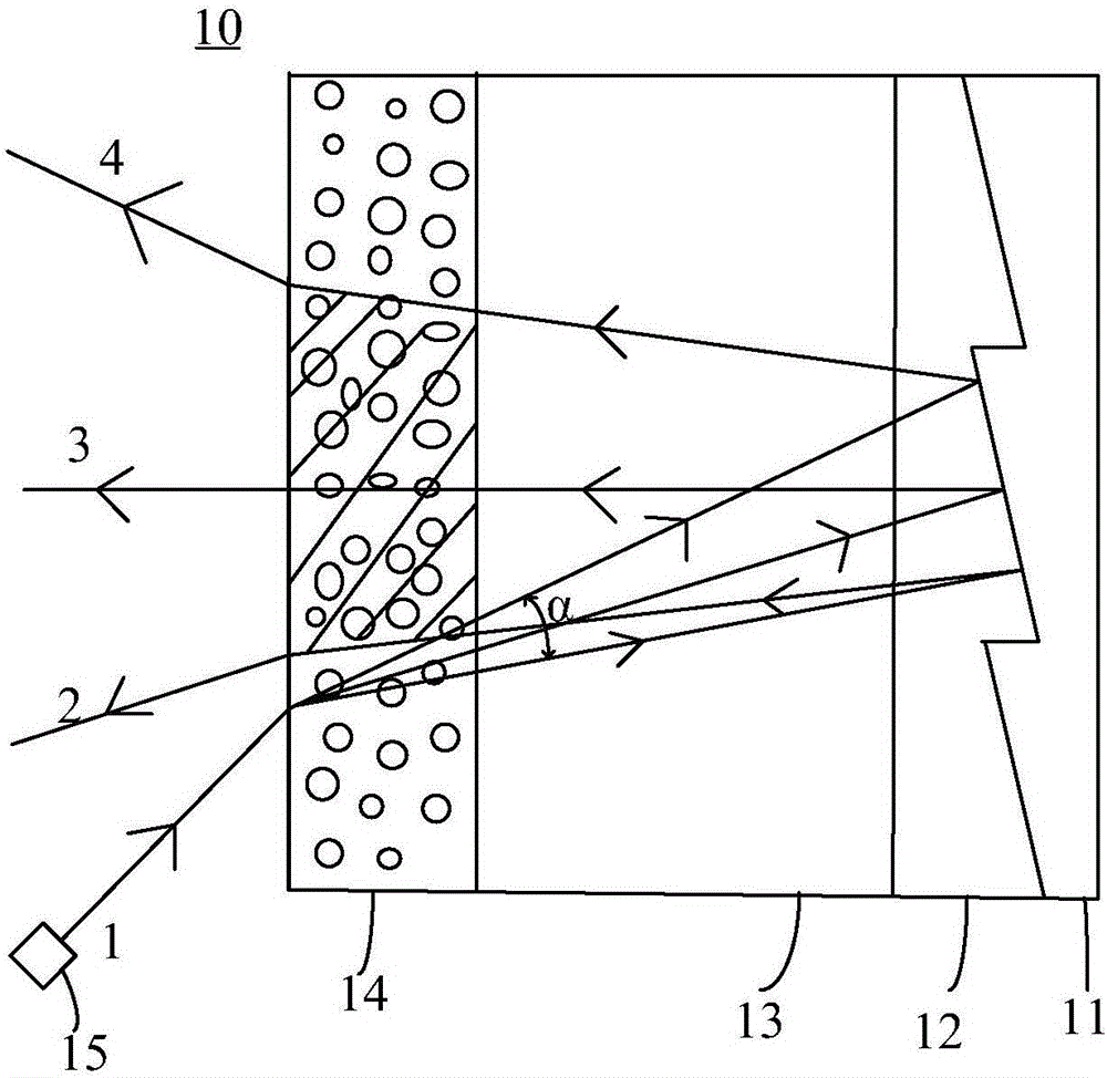
[0022] Such as figure 2 As shown in , it is a schematic structural diagram of the projection screen in Embodiment 1 of the present invention. The projection screen 10 is used to receive the image beam emitted by the projection device 15 , which includes a reflective layer 11 , a lens layer 12 , an isolation layer 13 and a scattering layer 14 , wherein the isolation layer 13 is located between the scattering layer 13 and the lens layer 14 .

[0023] The image beam passes through the scattering layer 14, the isolation layer 13, and the lens layer 12 sequentially after exiting the projection device 15, and reaches the reflective layer 11, and after being reflected by the reflective layer 11, it passes through the lens layer 12, the isolation layer 13, and the scattering layer again. After 14, it enters the human eye.

[00...

Embodiment 2

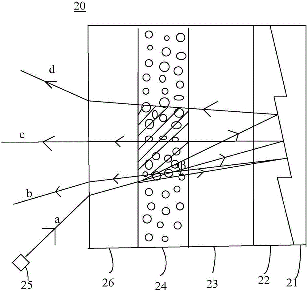
[0041] see image 3 , which is a schematic structural diagram of the projection screen according to Embodiment 2 of the present invention. The projection screen 20 is used to receive the image light beam emitted by the projection device 25, which includes a reflective layer 21, a lens layer 22, an isolation layer 23, a scattering layer 24 and a substrate layer 26, wherein the isolation layer 23 is located between the scattering layer 23 and the lens layer 24 between.

[0042] The image light beam passes through the substrate layer 26, the scattering layer 24, the isolation layer 23, and the lens layer 22 successively after being emitted from the projection device 25, and reaches the reflective layer 21, and after being reflected by the reflective layer 21, it passes through the lens layer 22 again, and the isolation layer 23. After the scattering layer 24 and the substrate layer 26 enter the human eye.

[0043] The function and structure of the lens layer 22 , the scattering...

Embodiment 3

[0056] The projection screen of the present invention can be suitable for ultra-short-focus laser projection display.

[0057] Such as Figure 4 As shown in , it is a projection schematic diagram of an ultra-short-focus projection system provided by the present invention. The present invention further provides an ultra-short-focus projection system 30 , which includes an ultra-short-focus projection device 31 and the above-mentioned projection screen 32 .

[0058] The ultra-short-throw projection device 31 is used to generate laser light and project the laser light on the projection screen 32 to form an image on the projection screen 32 . The ultra-short-throw projection device 31 may be a laser projector.

[0059] The ultra-short-focus projection system of the present invention can effectively suppress speckles and improve image quality by using the aforementioned projection screen.


PUM

PropertyMeasurementUnit
Thicknessaaaaaaaaaa
Thicknessaaaaaaaaaa
Thicknessaaaaaaaaaa

Abstract

The invention discloses a projection screen and an ultra-short-focus projection system. The projection screen receives image light beams emitted by a projection device, and comprises a reflecting layer, a lens layer, an isolation layer and a scattering layer, wherein the isolation layer is arranged between the scattering layer and the lens layer; the image light beams pass through the scattering layer, the isolation layer and the lens layer in sequence and reach the reflecting layer after being emitted from the projection device; and after being reflected by the reflecting layer, the image light beams pass through the lens layer, the isolation layer and the scattering layer again and then, enter the human eyes. The ultra-short-focus projection system comprises the ultra-short-focus projection device and the projection screen. Laser generated by the ultra-short-focus projection device is projected onto the projection screen to form an image on the projection screen. The projection screen and the ultra-short-focus projection system can obviously reduce speckles of the projection screen.

Description

technical field [0001] The invention relates to the field of projection display, in particular to a projection screen and an ultra-short-focus projection system with the projection screen. Background technique [0002] When performing projection display, a projector is generally used together with a projection screen, so that the projected image has higher color resolution, better color saturation, and higher brightness. [0003] Such as figure 1 As shown, it is a schematic structural diagram of a projection screen in the prior art. The projection screen 100 generally includes a substrate layer 101 , a scattering layer 102 , a lens layer 103 and a reflection layer 104 , wherein the scattering layer 102 is adjacent to the lens layer 103 . The light emitted by the projector 105 is refracted by the substrate layer 101 and then enters the scattering layer 102. The scattering layer 102 diffuses the light into a beam with a certain angle. After the scattering layer 102 passes thr...

Claims


Application Information

Patent Timeline
IPC IPC(8): G03B21/602G03B21/60
CPCG03B21/60G03B21/602
Inventor 赵飞刘显荣
Owner QINGDAO HISENSE LASER DISPLAY CO LTD
Why Eureka
Try Eureka