
Internal Combustion Engine Piston

Active Publication Date: 2010-09-16
HITACHI ASTEMO LTD
View PDF5 Cites 19 Cited by
  • Summary
  • Abstract
  • Description
  • Claims
  • Application Information

AI Technical Summary

Benefits of technology

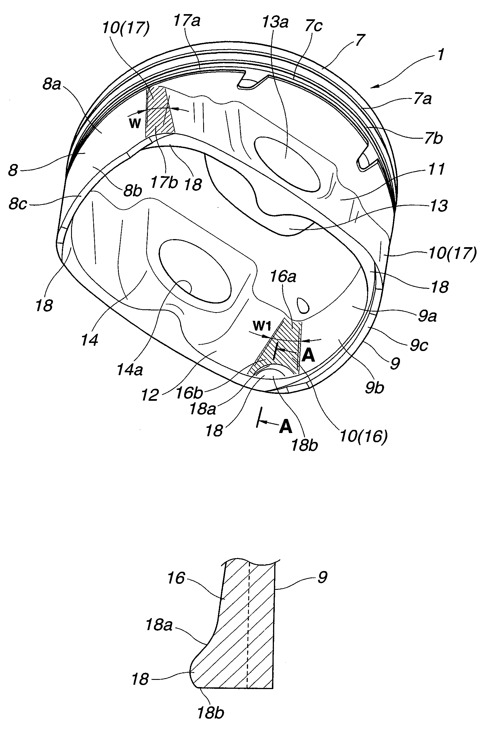
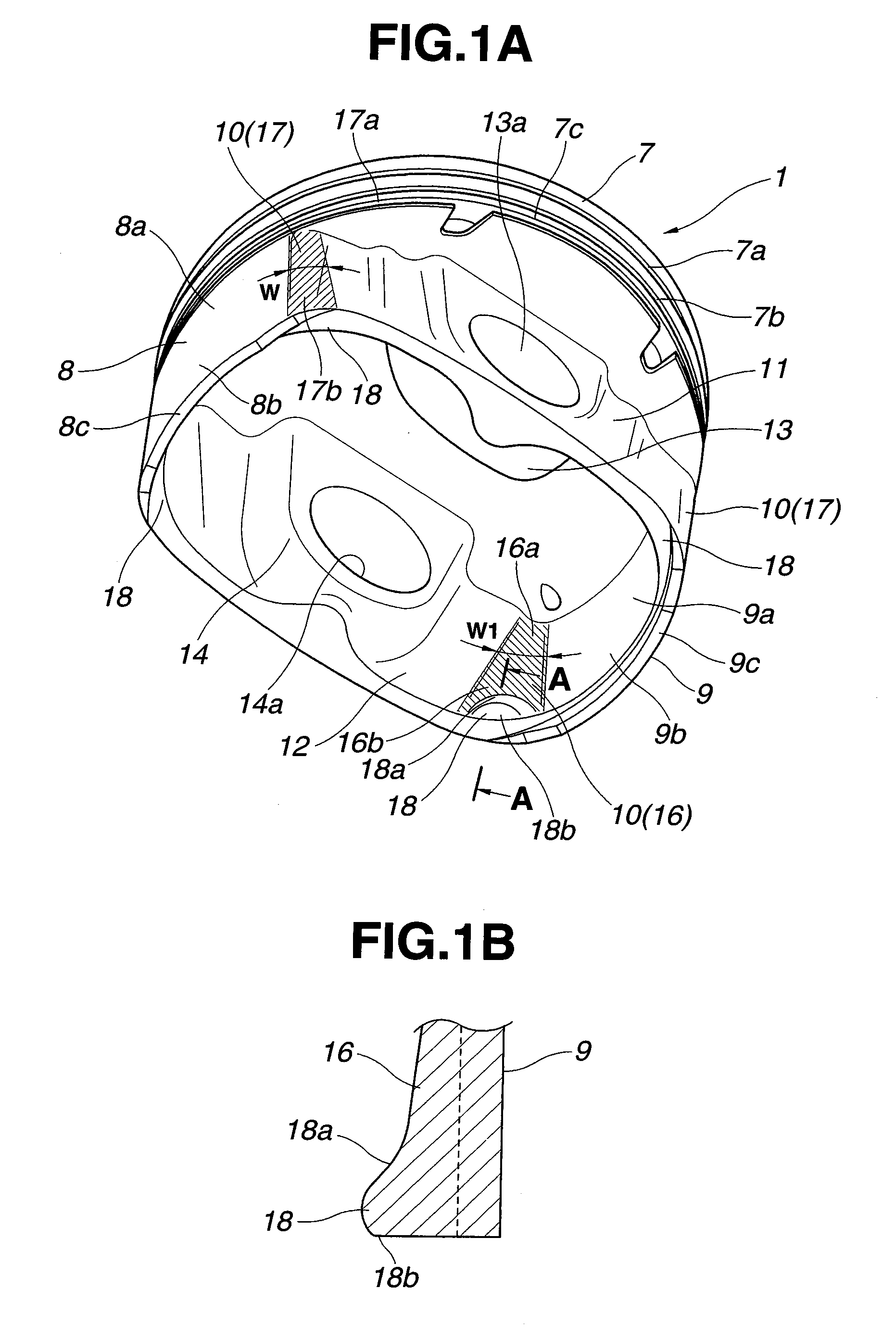
[0004]In the internal combustion engine piston according to Japanese Patent Application Publication No. 2008-190357, each stress dispersing portion is implemented by a projection which extends outwardly from a lower end portion of the corresponding skirt. This can enhance the rigidity of the lower end portion of the skirt locally, and thereby cause the rigidity of the entire skirt to be uneven. The contact pressure between each skirt and the cylinder wall can be locally high due to the uneven rigidity, so that the piston can be subject to a large frictional force.

Problems solved by technology

This can enhance the rigidity of the lower end portion of the skirt locally, and thereby cause the rigidity of the entire skirt to be uneven.
The contact pressure between each skirt and the cylinder wall can be locally high due to the uneven rigidity, so that the piston can be subject to a large frictional force.

Method used


Image

  • Internal Combustion Engine Piston
  • Internal Combustion Engine Piston
  • Internal Combustion Engine Piston

Examples


first embodiment

[0038]FIG. 8 shows a result of an experiment in which the amount of deformation of a thrust-side skirt at a point between the upper end and the lower end is measured under the same condition that the thrust-side skirt is in contact with cylinder wall 3 on expansion stroke, in a case of piston 1 which is indicated by a solid line, and in a case of a piston according to a reference example which is indicated by a broken line. In the piston according to the reference example, the amount of deformation significantly increases as the position moves from the upper end to the lower end. In contrast, in piston 1 according to the present embodiment, the amount of deformation is smaller and more uniform all over the range between the upper end and the lower end, although it is slightly relatively large at a position slightly below the upper end, and at or near the lower end. This is achieved because the characteristic shape of connecting section 10, and the provision of projection 18 serve t...

second embodiment

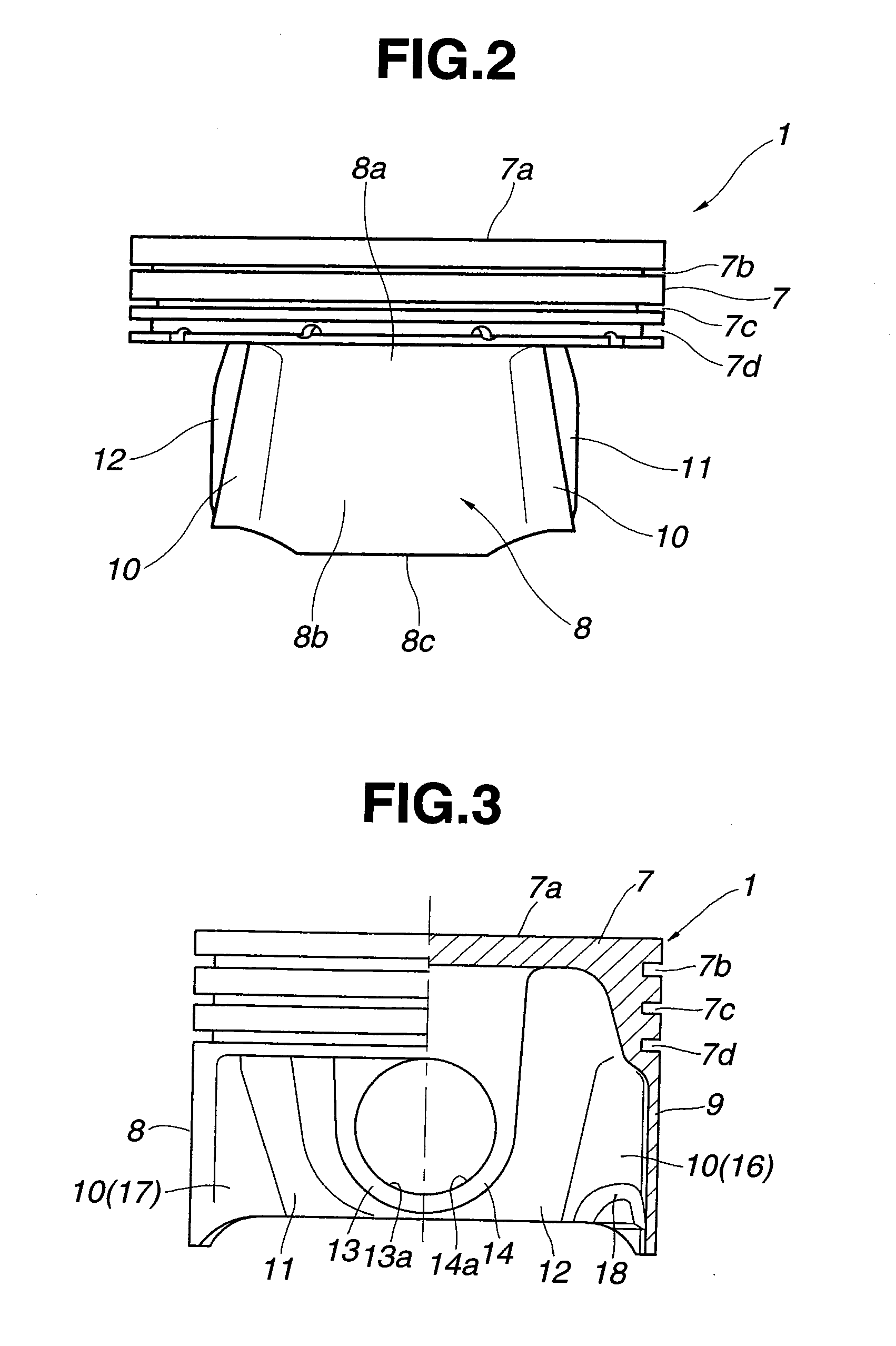
[0040]FIGS. 10 and 11 show a second embodiment in which thrust-side and anti-thrust-side skirts 8 and 9 are formed and arranged asymmetrically with respect to the plane passing through the central longitudinal axis of piston 1. Specifically, the circumferential length X of anti-thrust-side skirt 9 is set shorter than the circumferential length X1 of thrust-side skirt 8. Namely, the contact area of anti-thrust-side skirt 9 with cylinder wall 3 is set smaller than that of thrust-side skirt 8. This is because the pressing force applied to anti-thrust-side skirt 9 is smaller than the pressing force applied to thrust-side skirt 8.

[0041]The radius of curvature of each of two connecting sections 10 closer to thrust-side skirt 8 is set equal to that in the first embodiment. On the other hand, the radius of curvature of each of two connecting sections 10a closer to anti-thrust-side skirt 9 is set smaller than that of connecting sections 10 closer to thrust-side skirt 8.

[0042]Moreover, the th...


PUM


Abstract

An internal combustion engine piston includes a piston crown, a thrust-side skirt, an anti-thrust-side skirt, a first apron, and a second apron. The first and second aprons are connected to the thrust-side and anti-thrust-side skirts through connecting sections. Each connecting section has a thickness that gradually increases as followed from a proximal longitudinal end to a distal longitudinal end, wherein the proximal longitudinal end is closer to the piston crown, and the distal longitudinal end is closer to a distal longitudinal end of a corresponding one of the thrust-side and anti-thrust-side skirts.

Description

BACKGROUND OF THE INVENTION[0001]The present invention relates to internal combustion engine pistons which may be adapted to motor vehicles.[0002]In an internal combustion engine, a piston is subject to high combustion pressure, and thereby subject to a side force because of inclination of a connecting rod with respect to the piston. The side force presses the piston on a cylinder wall, and causes a large frictional force between a thrust-side skirt of the piston and the cylinder wall. Accordingly, internal combustion engine pistons are designed to bear such side forces, and reduce such frictional forces. On the other hand, there is demand for weight reduction of internal combustion engine pistons.[0003]Japanese Patent Application Publication No. 2008-190357 discloses an internal combustion engine piston which includes a thrust-side skirt, an anti-thrust-side skirt, and a pair of aprons between the thrust-side skirt and the anti-thrust-side skirt, where each connecting section betwe...

Claims


Application Information

Patent Timeline
IPC IPC(8): F02F3/00
CPCF02F3/02F02F3/00
Inventor IWATA, KAZUYASUE, SEIICHI
Owner HITACHI ASTEMO LTD
Learn More