Breech seal for air gun

a technology of air guns and seals, which is applied in the field of barrels and breech seals, can solve the problems of reducing smoothness and difficult shooting accuracy of air guns

Inactive Publication Date: 2010-09-16
GORE THOMAS
View PDF2 Cites 15 Cited by
  • Summary
  • Abstract
  • Description
  • Claims
  • Application Information

AI Technical Summary

Problems solved by technology

However, the use of an increased port cross-sectional area often generates increased physical shock as the piston slams into the end of the compression bore due to a reduction in piston back-pressure, such that the air gun is more difficult to shoot accurately, and with reduced smoothness.

Method used


Image

  • Breech seal for air gun
  • Breech seal for air gun
  • Breech seal for air gun

Examples


Embodiment Construction

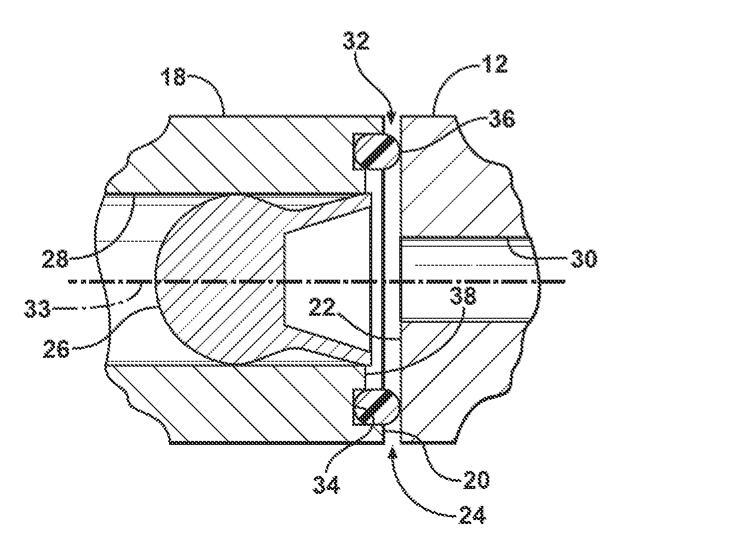
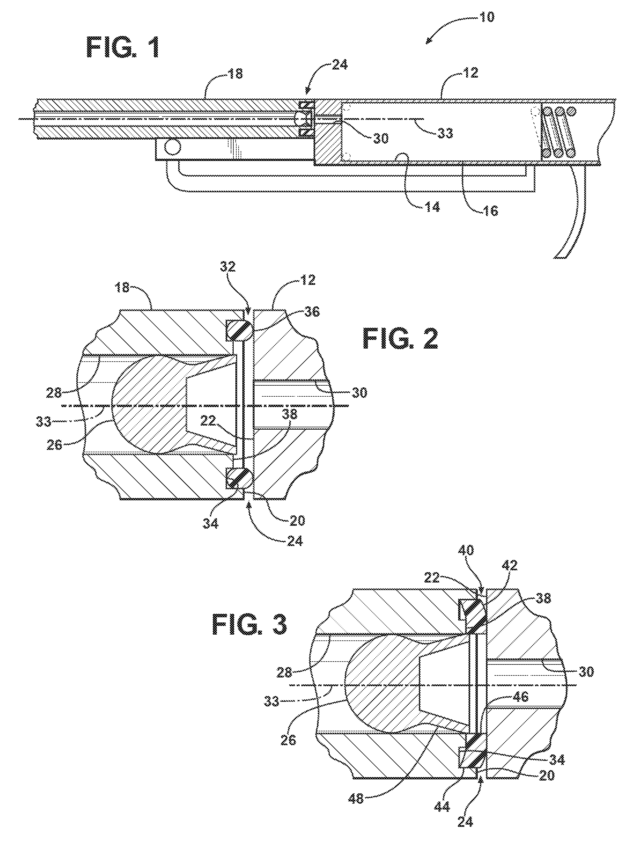
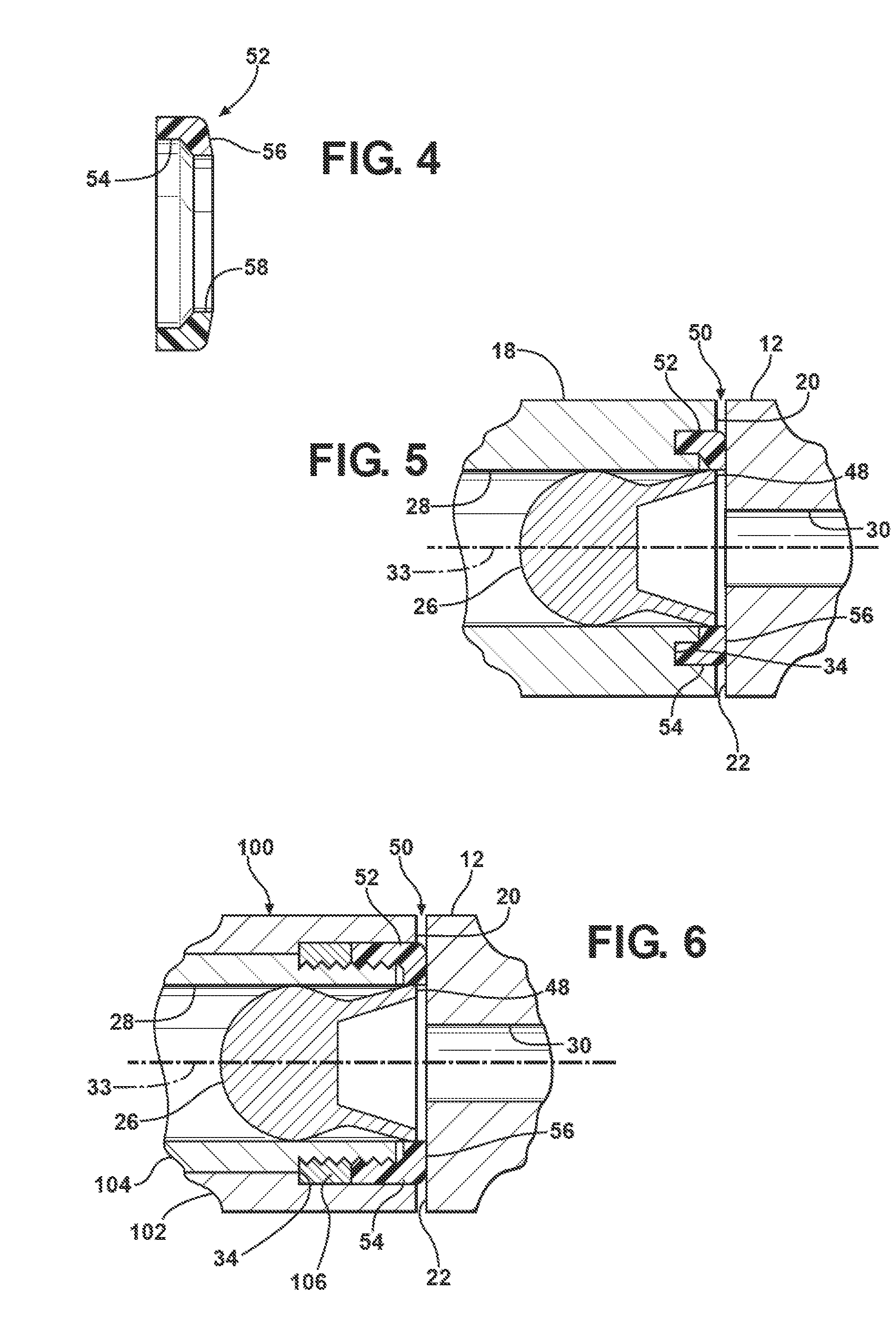
[0018]Referring to FIGS. 1 and 2, a break barrel air gun 10 includes a receiver 12 defining an internal compression chamber 14 for generating a quantity of compressed gas upon powered translation of a piston 16 within the chamber 14. The piston 16 may be powered by a coil spring, a gas spring, compressed gas, or some other power source suitable for the air gun 10. A barrel 18 is pivotally mounted on an end of the receiver 12, such that a barrel face 20 defined on a rearward end of the barrel 18 is pivoted away from a breech face 22, which is defined on a forward rend of the receiver 12, to provide access to a breech 24, whereby a pellet 26 can be loaded into the breech 24. When closed to place the barrel face 20 in general parallel-spaced opposition with the breech face 22, a barrel bore 28, which extends along a longitudinal axis 33, is placed in general axial alignment with a gas transfer port 30 that is defined in the breech face 22, by which compressed air is delivered from the ...


PUM


Abstract

A barrel break air gun includes a pair of opposed, generally planar faces defining a narrow gap between the breech and the barrel. The barrel face includes a circular groove concentric with the barrel bore that receives an annular seal, and a recessed annular land defined between the circular groove and the barrel bore. The annular seal may be either an o-ring nominally disposed within the circular groove, or an annular urethane washer that is slightly radially-compressed when placed into the circular groove such that the inner diameter of the washer projects slightly away from the barrel face prior to closing the barrel breech. In one embodiment featuring the annular washer, the washer's internal diameter is slightly smaller than the maximum skirt dimension of an air gun pellet, such that the pellet's skirt is retained by the washer upon closing the barrel breech.

Description

CROSS-REFERENCE TO RELATED APPLICATIONS[0001]This application claims the benefit if U.S. Provisional Patent Application Ser. No. 61 / 160,702, filed on Mar. 16, 2009, the disclosure of which is hereby incorporated by reference.TECHNICAL FIELD[0002]This invention relates to air guns and, particularly, to a barrel and breech seals for such air guns.BACKGROUND OF THE INVENTION[0003]Known barrel break air guns fire projectiles using compressed air that is delivered to a gas transfer port disposed in the gun breech, immediately rearward of a projectile, such as a pellet, disposed in the barrel proximate to the breech. The barrel is pivotally connected to the breech, such that the barrel can be “broken” to expose the rearward extent of the barrel's bore in order to receive the pellet, whereupon the pellet is retained in the rearward extent of the barrels' bore by static friction until firing.[0004]The opposed generally planar faces of the breech and the barrel are typically sealed by an o-r...

Claims


Application Information

Patent Timeline
Patent Type & Authority Applications(United States)
IPC IPC(8): F41B11/34F41B11/00F41B11/73
CPCF41B11/73F41B11/642
Inventor GORE, THOMAS
Owner GORE THOMAS
Why Eureka
Try Eureka