Extended flange plumbing for deep-sea oil containment

a technology of extended flanges and oil containment, which is applied in the direction of hose connections, borehole/well accessories, mechanical equipment, etc., can solve the problems of complicated view, reduce the risk of further damage to the bop, reduce the amount of special equipment, and reduce the risk and response time

Inactive Publication Date: 2011-12-15
COMMONER FREDERIC G
View PDF1 Cites 30 Cited by
  • Summary
  • Abstract
  • Description
  • Claims
  • Application Information

AI Technical Summary

Benefits of technology

[0045]It is an object of the invention to enable a leak from a compromised BOP to be quickly capped, so that oil flow is either blocked entirely, or extracted without significant release.
[0046]Another object of the invention is to reduce the risk of further damage to the BOP by permitting the capping of a BOP without the need to make intrusive emergency BOP modifications, such as removal of parts.
[0047]An additional object of the invention is to provide a capping process which is ROV-friendly, in the sense that it can be easily performed by underwater Remotely Operated Vehicles.
[0048]A further ob

Problems solved by technology

It's a complicated view, when seen directly from the side.
Howeve

Method used


Image

  • Extended flange plumbing for deep-sea oil containment
  • Extended flange plumbing for deep-sea oil containment
  • Extended flange plumbing for deep-sea oil containment

Examples


Embodiment Construction

—Structure

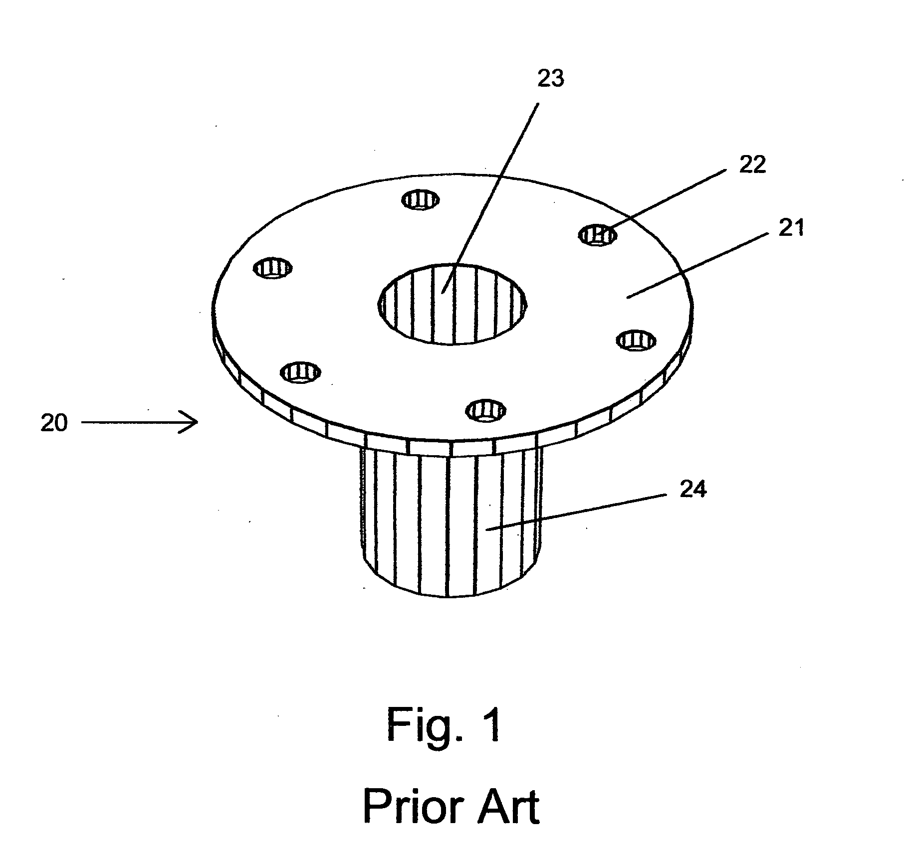
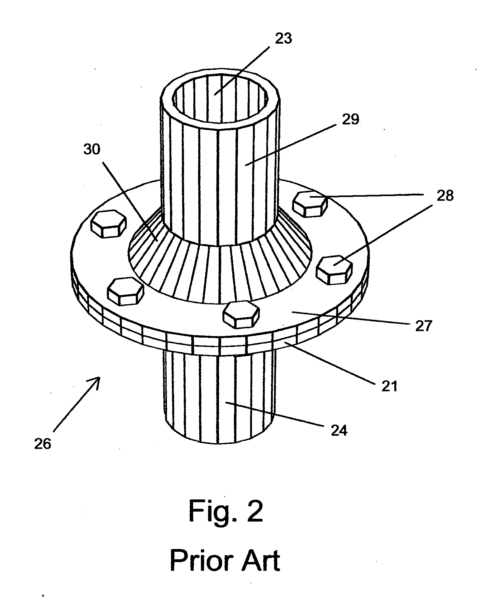
[0072]In order to properly understand the present invention, it is helpful to compare it to a standard industrial plumbing flange of the prior art, shown in FIGS. 1, 2, and 3.

Prior Art Flanges

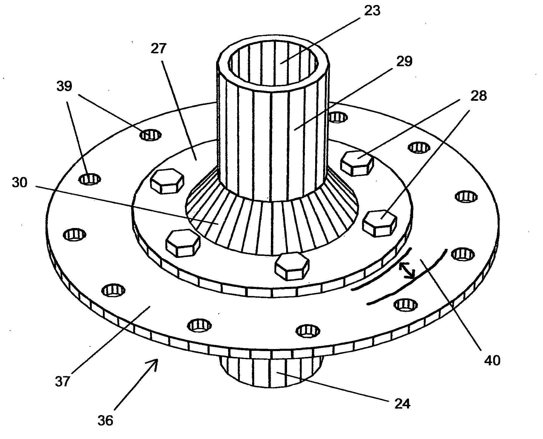
[0073]FIG. 1 shows a prior art plumbing flange 20. It has a horizontal plate 21 used to create a seal with a matching plate on a matching flange. The plate has a plurality of bolt holes 22 through which bolts will be placed to fasten the top and bottom flanges, and to apply sealing pressure. A flow opening 23 allows for passage of fluid through the flange, while a shaft 24 provides a means of attachment onto a pipe, normally by welding or screwing the pipe into place. (The flange of FIG. 1 also has a support collar which is hidden, in this view, by the plate. The support collar will be visible in FIG. 3.) The shaft 24 will also be referred to as a “lower shaft” when the flange 20 of which it is a part is the lower of two flanges in an assembled flange joint. Similarly, the horizontal ...


PUM


Abstract

An emergency redundant mounting flange is provided for incorporation into an oil-well blow-out-preventer (BOP), enabling rapid, tight-fitting attachment of an oil containment cap over a BOP outflow port in an emergency. This flange extends radially outward from the protected port, and includes an annular region with a connection feature, such as a ring of bolt-holes, permitting cap attachment. The cap, also provided, is a barrel-shaped diameter-reduction pipe which can be connected onto the emergency mounting flange at its bottom end, and onto a standard riser pipe at its top end, thus containing or stopping the flow of oil. After installation, the cap fully encloses the protected port, while creating a tight seal with the emergency mounting flange. Extension of these methods to bell-and-spigot plumbing fixtures, including reinforced concrete pipe, is also provided.

Description

CROSS-REFERENCE TO RELATED APPLICATIONS [0001]This application claims the benefit of provisional patent application Ser. No. 61 / 397,288, filed on Jun. 9, 2010 by the present inventor.FIELD OF THE INVENTION [0002]The present invention relates to the containment of oil-leaks from blown-out oil wells, and, more particularly, to the attachment of an oil-containment cap to a leaking oil well by means of an extended flange fixture incorporated into the blow-out preventer.REFERENCE DOCUMENTS [0003][Cameron]“Considering Technical Options for controlling the BP blowout in the Gulf of Mexico”, James Cameron's Ad Hoc Deep Ocean Group, Jun. 1, 2010. http: / / www.whoi.edu / fileserver.do?id=64963&pt=10&p=44453[0004][Hammer]“Discovery of second pipe in Deepwater Horizon riser stirs debate among experts”, David Hammer, The Times-Picayune, Jul. 9, 2010. http: / / www.nola.com / news / gulf-oil-spill / index.ssf / 2010 / 07 / post—19. html[0005][Mowbray]“BP removes containment cap in preparation for method that could ...

Claims


Application Information

Patent Timeline
IPC IPC(8): F16L23/00F16L21/02
CPCE21B43/0122F16L55/115F16L23/032
Inventor COMMONER, FREDERIC G.
Owner COMMONER FREDERIC G
Why Eureka
Try Eureka