Ratchet-type buckle and snowboard binding

Inactive Publication Date: 2006-08-08
K 2 CORP
View PDF19 Cites 30 Cited by
  • Summary
  • Abstract
  • Description
  • Claims
  • Application Information

AI Technical Summary

Benefits of technology

[0010]The present invention is directed to a buckle for engaging a ladder strap that provides a ratchet mechanism that facilitates tightening the strap, and that relatively easily releases the strap. The ratchet-type buckle includes a base the receives the strap, a pair of oppositely disposed sidewalls, and a strap engagement member rotatably mounted to the sidewalls. The strap engagement member is movable between a first and a second

Problems solved by technology

A holding pawl permits forward rotation of the strap engagement member

Method used


Image

  • Ratchet-type buckle and snowboard binding
  • Ratchet-type buckle and snowboard binding
  • Ratchet-type buckle and snowboard binding

Examples


first embodiment

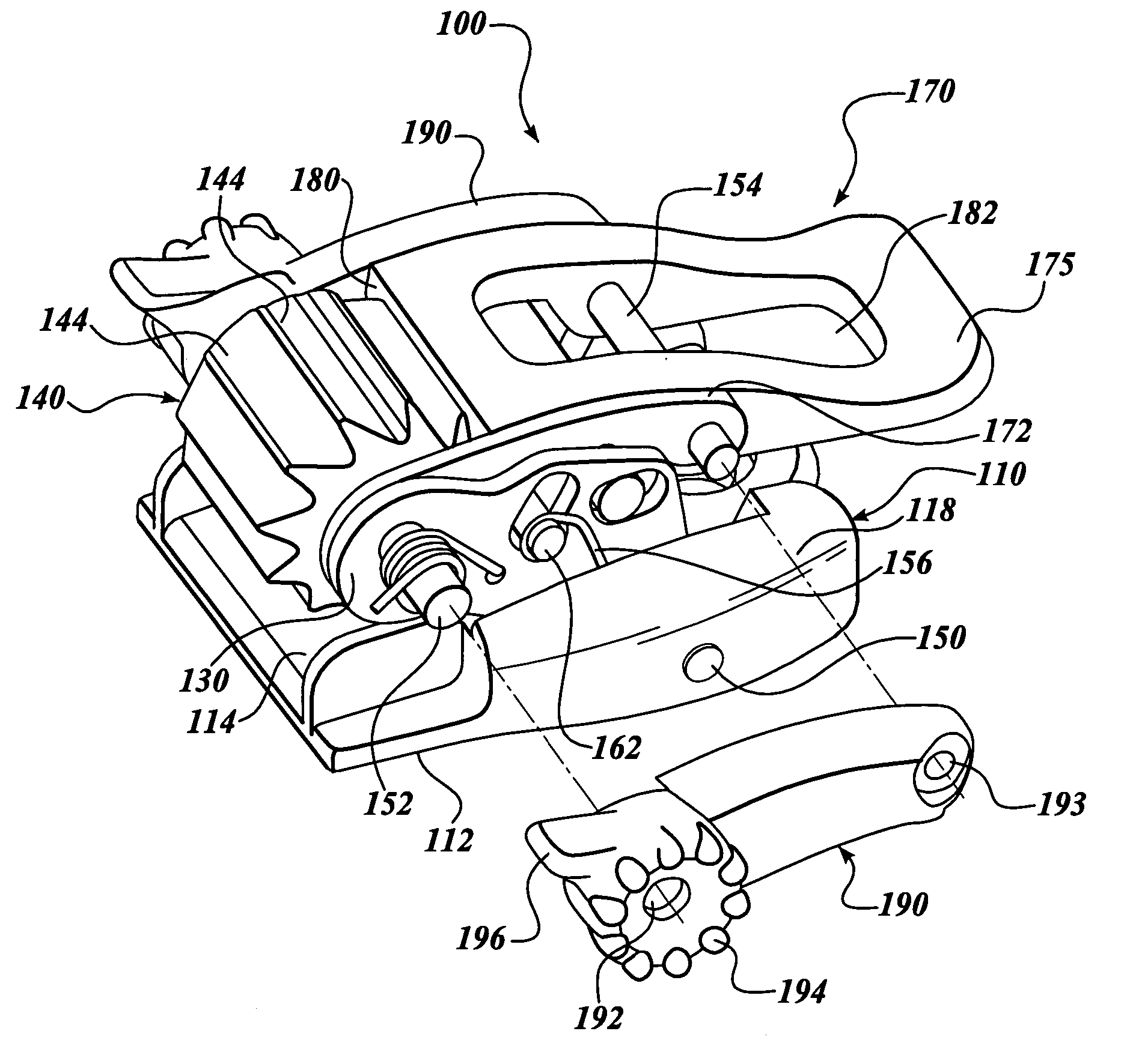
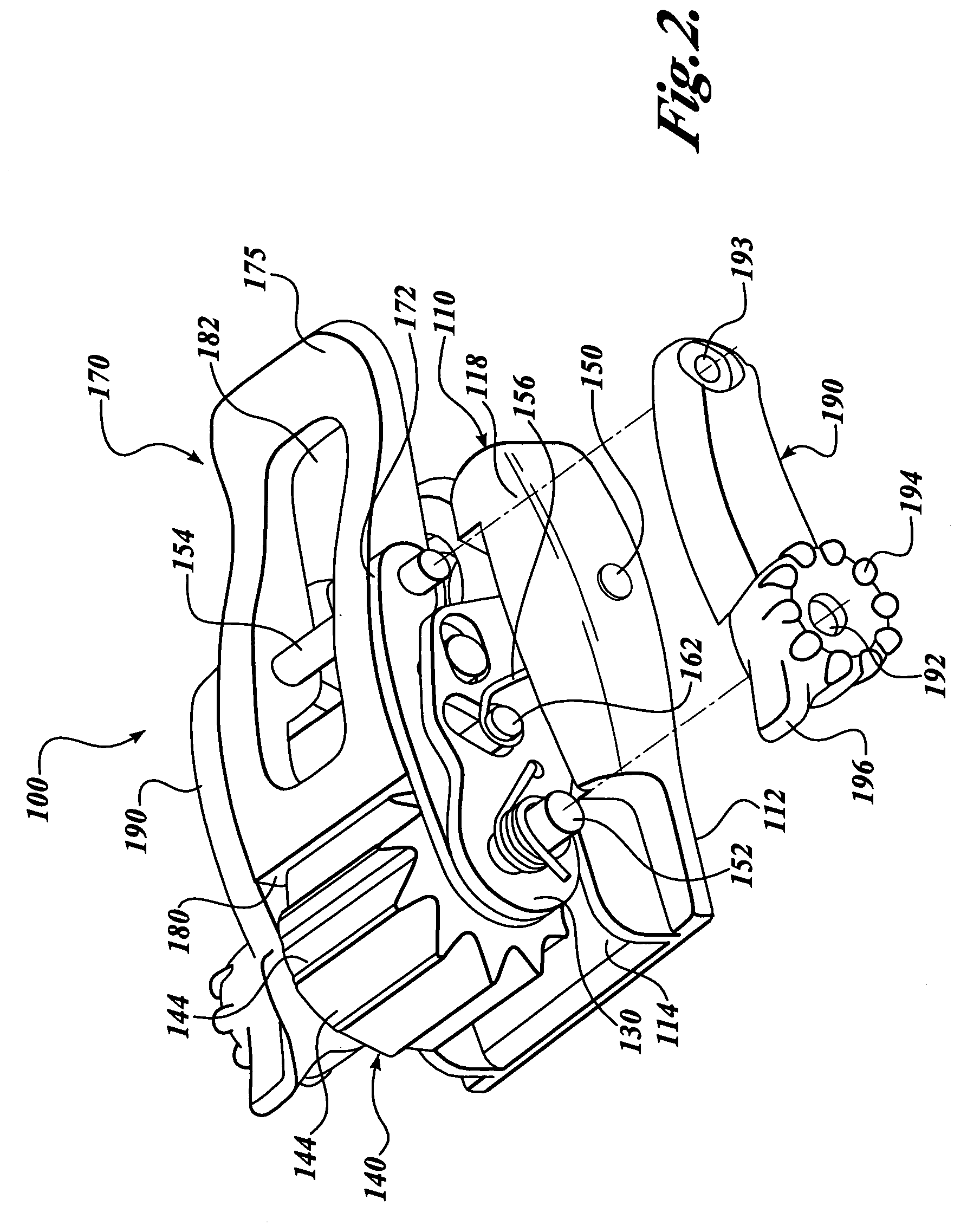
[0039]Another embodiment of a buckle according to the present invention is shown in FIG. 6, which shows a buckle 200 having a one-piece lever 270. The base 110, sidewalls 130, toothed barrel 140, and holding pawl 160 are generally the same as that described above. The lever 270 is preferably of unitary construction, having a proximal end 272 having oppositely disposed elongate transverse apertures 273 (one shown) that rotatably engage the barrel pivot pin 152. Release tabs 296 disposed at the proximal end 272 facilitate gripping of the lever 270 for releasing the strap, similar to the first embodiment described above. The elongate apertures 273 permit the lever proximal end 272 to be slidably moved between a first (lower) position and an second (upper) position (the lever 270 is shown in the first position in FIG. 6). The lever 270 includes a center pawl portion 280 that is located such that when the lever proximal end 272 is in the first position, the pawl portion 280 engages the b...

third embodiment

[0043]a buckle according to the present invention is shown in FIG. 7, which shows a buckle 300 having a base 110, sidewalls 130, and toothed barrel 140 substantially the same as described above. The holding pawl 360 is also similar to the holding pawl 160 described above, and functions in substantially the same manner. The holding pawl 360, however, is unitary in construction, which may be less expensive to manufacture and assembly.

[0044]In this third embodiment, a lever assembly 370 includes a lever body 375 having a proximal end 372 with oppositely disposed transverse apertures 373 that pivotally engage the barrel pivot pin 152. The lever body 375 includes a distal portion 376 and a central portion 378. The central portion 378 includes a cavity 371 disposed generally adjacent the barrel 140. A driving pawl member 390 is slidably and springedly captured within the rectangular cavity 371, the driving pawl member 390 being elastically biased towards the barrel 140, and positioned suc...


PUM


Abstract

A ratchet-type buckle (100) is disclosed for use with a ladder strap (80), wherein the buckle includes a toothed, barrel-shaped strap engagement member (140) that is rotatably mounted between oppositely disposed sidewalls (130) that are pivotally coupled to a base (110). The engagement member is positioned to drivably engage and hold the strap. A holding pawl (160) allows forward rotation and hinders backward rotation of the engagement member. A driving pawl (180) is incorporated into a lever assembly (170), which is pivotally coupled to the sidewalls, the driving pawl positioned to engage and rotate the engagement member teeth when the lever assembly is pivoted in a forward direction. The pivotal coupling of the sidewalls to the base permit the engagement member to be lifted away from the base, to release the strap. The sidewalls are preferably biased towards the base.

Description

CROSS-REFERENCES TO RELATED APPLICATIONS[0001]This application is a continuation of application Ser. No. 10 / 220,182, filed Aug. 27, 2002, which is the national stage of International Application No. PCT / US01 / 17796, filed May 31, 2001, which claims the benefit of Provisional Patent Application No. 60 / 208,136, filed May 31, 2000, both of which are incorporated herein by reference.FIELD OF THE INVENTION[0002]This invention relates to bindings used for sports equipment and, more particularly, to ratchet-type buckles used in such bindings.BACKGROUND OF THE INVENTION[0003]In many sports, for example, winter sports such as snowboarding and skiing, users bind their boots to a sporting apparatus such as a pair of skis or a snowboard. Conventional snowboard bindings are generally classified as either high back bindings or plate or step-in bindings. In such bindings, it is generally desirable to have a comfortable and secure attachment to the apparatus that is easily engaged and disengaged. Al...

Claims


Application Information

Patent Timeline
IPC IPC(8): A43C11/00A43C11/14A44B11/12A44B11/14
CPCA43C11/1406A43C11/146A44B11/125A44B11/14A63C10/06Y10T24/3703Y10T24/2106Y10T24/216Y10T24/2183Y10T24/21Y10S24/909
Inventor LIVINGSTON, DAVID
Owner K 2 CORP
Why Eureka
Try Eureka