Strap tensioner

a strap tensioner and strap technology, applied in the field of strap tensioners, can solve the problems of difficult to loosen the strap from the buckle, inability to hold the grip, and often insufficient grip of the user's strap, so as to facilitate the use of the tension lever, facilitate the use of the strap, and quickly pull the strap.

Inactive Publication Date: 2005-03-22
RARD ROY
View PDF12 Cites 33 Cited by
  • Summary
  • Abstract
  • Description
  • Claims
  • Application Information

AI Technical Summary

Benefits of technology

It is another object of the present invention to provide such a device that enables the user to easily tighten the strap to the desired amount of tension.
It is a further object of the present invention to provide such a device that also allows the strap to be easily loosened after being shortened or tightened to a desired amount.
Because the tension lever and intermediate member are selectively engaged to bind to the strap, the user may easily use the tension lever to quickly pull the strap through the slot formed between the second cam surface and the flange member. Because the brake member is biased in a closed position to hold the strap as the tension lever is moved in a forward direction, the strap is prevented from being pulled back through the rigid base as the strap is tightened. Also, because the brake lever is biased in the closed position, the strap may be easily loosened by rotating the brake member forward to the opened position. Because the tension lever can be used to open the brake lever, the user may intermittently loosen the strap by rotating the tension lever to tap or slightly move the brake lever between closed and opened positions.
In summary, the improved strap tensioner allows the user to easily tighten a strap by simply moving the tension lever back and forth over the rigid base. Because the tension lever may be selectively bound to the strap, and because the brake lever prevents the strap from being pulled through the rigid base, greater tension may be applied to the strap of the strap tensioner than to a standard buckle. The user may easily loosen the strap by simply moving the brake lever to the unlocked position or by using the tensioning lever to intermittently control the brake lever.

Problems solved by technology

Unfortunately, the user is often unable to grip the loose end of the strap sufficiently to tighten the strap to the desired length or tension, or the buckle is unable to hold its grip and is slowly pulled towards the loose end of the strap.
Even when the working end of the strap could be tightened to the desired length or tension, it is often difficult to loosen the strap from the buckle.

Method used


Image

  • Strap tensioner
  • Strap tensioner
  • Strap tensioner

Examples


Embodiment Construction

)

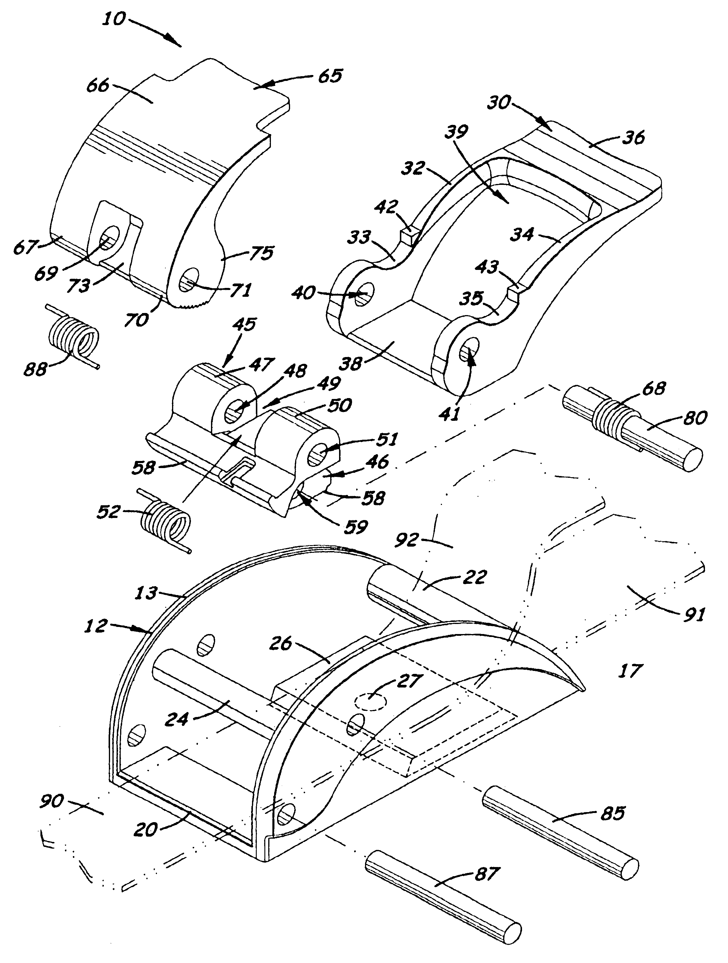
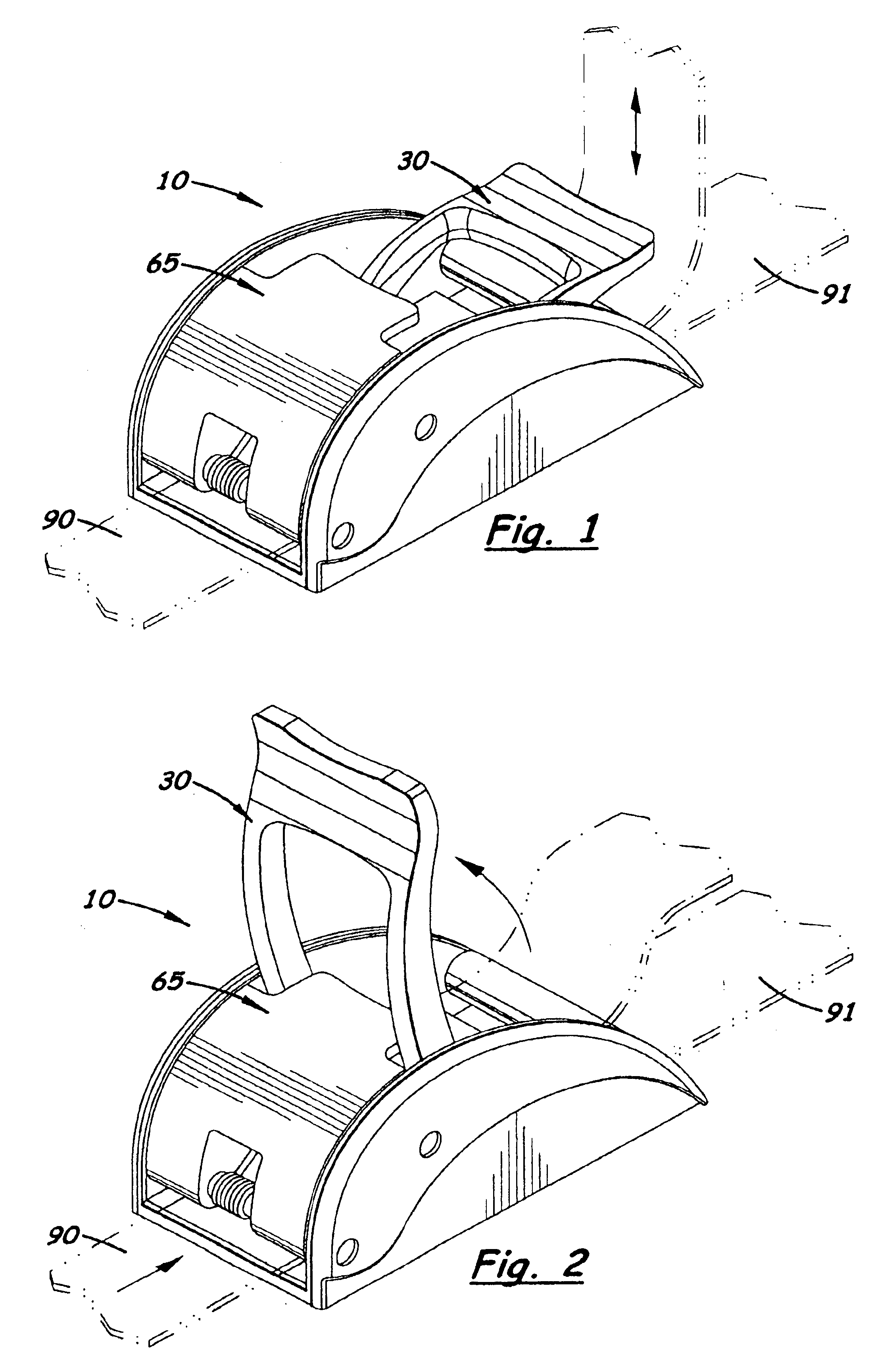
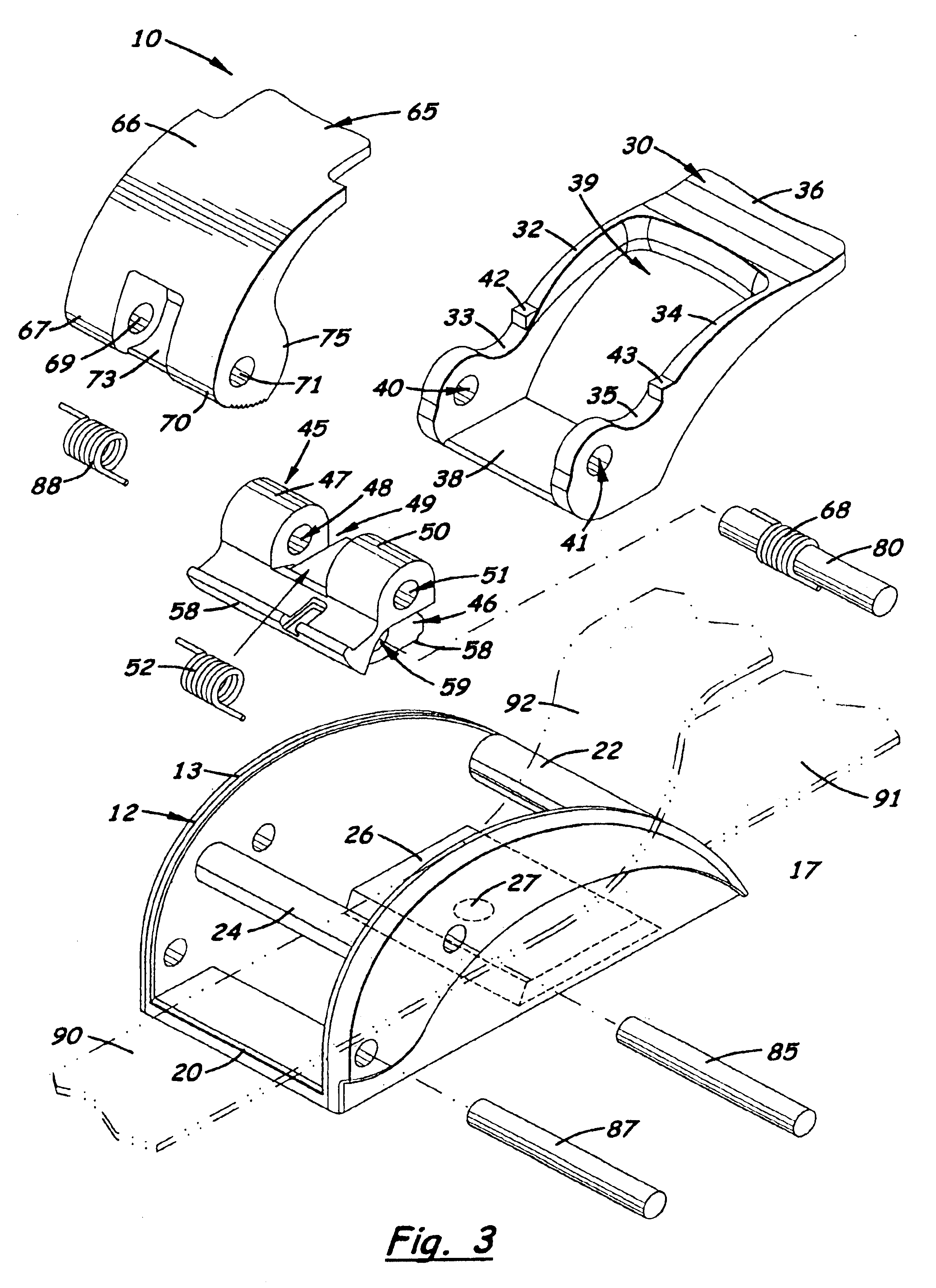
Referring to the accompanying FIGS. 1-12, wherein like reference numbers refer to like components, there is shown an improved strap tensioner 10 designed to allow a user to manually tighten the strap 90 by applying greater tension to a strap 90 than buckles or other strap tensioners that exist in the prior art.

As shown in FIG. 3, the strap tensioner 10 includes a rigid base 12 upon which the strap 90 is longitudinally extended over. The rigid base 12 includes two parallel, longitudinally aligned side walls 13, 17 connected together by a front flange member 20, a rear strut 22, an upper strut 24, and a rear flange member 26. The non-working end 91 of the strap 90 or one end of a second strap (not shown) is securely wrapped around the rear strut 22 to securely connect the rigid base 12 thereto. The free or working end 92 of the strap 90 enters the distal end and exits the proximal end of the tensioner 10. An optional hole 27 is formed in the rear flange member 26 that enables the rig...


PUM

PropertyMeasurementUnit
tensionaaaaaaaaaa
distanceaaaaaaaaaa
movementaaaaaaaaaa

Abstract

An improved strap tensioner that allows a user to manually shorten the strap by applying greater tension on the strap and easily lengthening the strap after being tightened. The tensioner includes a tension lever, an intermediate member, and a brake lever all pivotally mounted on a rigid base. The tension lever and brake member are longitudinally aligned on opposite sides of the rigid base. Formed on the tension lever is a transversely aligned clamping flange that extends under the strap when longitudinally extended through the rigid base. Formed on the intermediate member and disposed above the clamping flange is a first cam surface that forms a slot for the strap to extend through. The brake lever includes a second cam surface that is spaced above the front flange member to form a second slot. During operation, the brake lever is rotated to press the second cam surface against the front flange member to temporarily hold the strap inside the rigid base. During use, the tension lever, the intermediate member and the brake lever are sequentially coupled together to selectively engage, pull and release the strap allowing the strap to be tightened or loosened.

Description

BACKGROUND OF THE INVENTION1. Field of the InventionThis invention relates to devices used to tighten a strap, and more particularly, to such devices that enable the user to apply greater tension to the strap.2. Description of the Related ArtAdjustable buckles used to tighten a strap around an object or to attach the ends of two straps together are very common. Typically, such buckles include an outer frame made of metal or plastic with one or more transversely aligned round pins that the loose end of the strap wraps around and binds against to hold the strap at a desired tension or length. In order to tighten the strap, the loose end or “bitter end” of the strap must be pulled in a direction opposite the direction to the strap. Unfortunately, the user is often unable to grip the loose end of the strap sufficiently to tighten the strap to the desired length or tension, or the buckle is unable to hold its grip and is slowly pulled towards the loose end of the strap. Even when the wor...

Claims


Application Information

Patent Timeline
Patent Type & Authority Patents(United States)
IPC IPC(8): A44B11/12A44B11/00B60P7/08B60P7/06
CPCA44B11/125B60P7/083Y10T24/404Y10T24/45775Y10T24/3404Y10T24/4773Y10T24/4016Y10T24/4072
Inventor RARD, ROY
Owner RARD ROY
Why Eureka
Try Eureka