Fastening sockets, washers and fasteners used with the washers and the fastening sockets

a technology for fastening sockets and washers, applied in the field of fastening sockets, can solve the problems of difficult positioning of washers, operator's inability to see, and their positions are not free and dependent from each other, and achieve the effect of easy tightening

Inactive Publication Date: 2014-01-21
YUNITAITO
View PDF12 Cites 29 Cited by
  • Summary
  • Abstract
  • Description
  • Claims
  • Application Information

AI Technical Summary

Benefits of technology

[0011]The present invention addresses the above described problems, and one object of the present invention is to provide a fastening socket and a washer for receiving counter torque that allows easy tightening of a nut (or a bolt head) to be tightened through only positioning of the nut. Another object of the present invention is to provide a fastener by which a nut can be tightened onto a bolt without “simultaneous bolt-nut rotation” using the fastening socket and the washer for receiving counter torque.

Problems solved by technology

Furthermore, since the inner socket portion and the outer socket portion are coupled with a gear mechanism, their positions are not free and dependent from each other.
Furthermore, setting of their positions must be performed inside the socket, where an operator is not able to see.
For these reasons, the positioning of them is very difficult to perform, particularly in a bad foothold or in a narrow space.
As a result, workability is remarkably worsened.
Furthermore, if the electrical tool is operated while the inner socket portion is engaged with the nut (or the bolt head) without positioning of the outer socket portion with respect to the washer, the washer or the outer socket portion may be damaged.
The work under such a condition is extremely inefficient.

Method used


Image

  • Fastening sockets, washers and fasteners used with the washers and the fastening sockets
  • Fastening sockets, washers and fasteners used with the washers and the fastening sockets
  • Fastening sockets, washers and fasteners used with the washers and the fastening sockets

Examples


embodiment 1

[0061

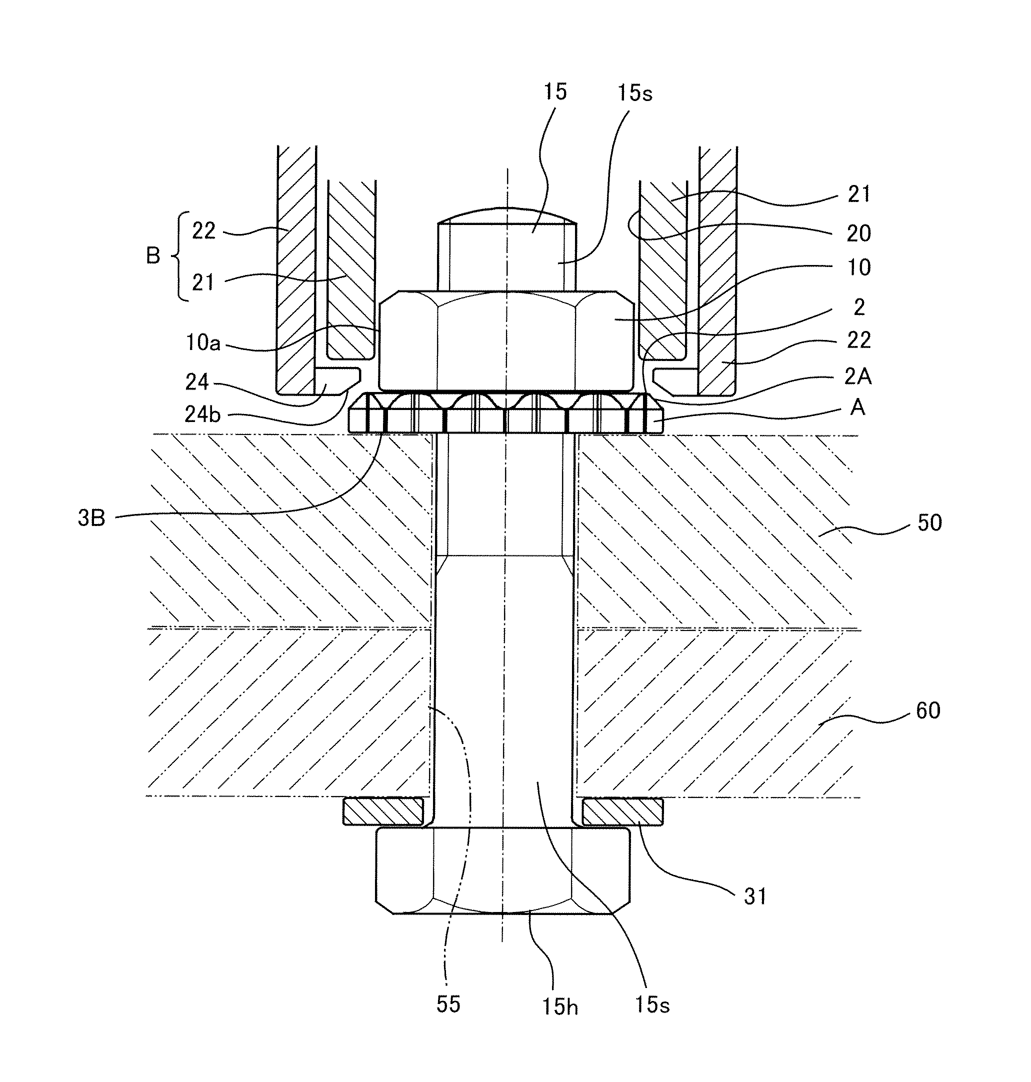
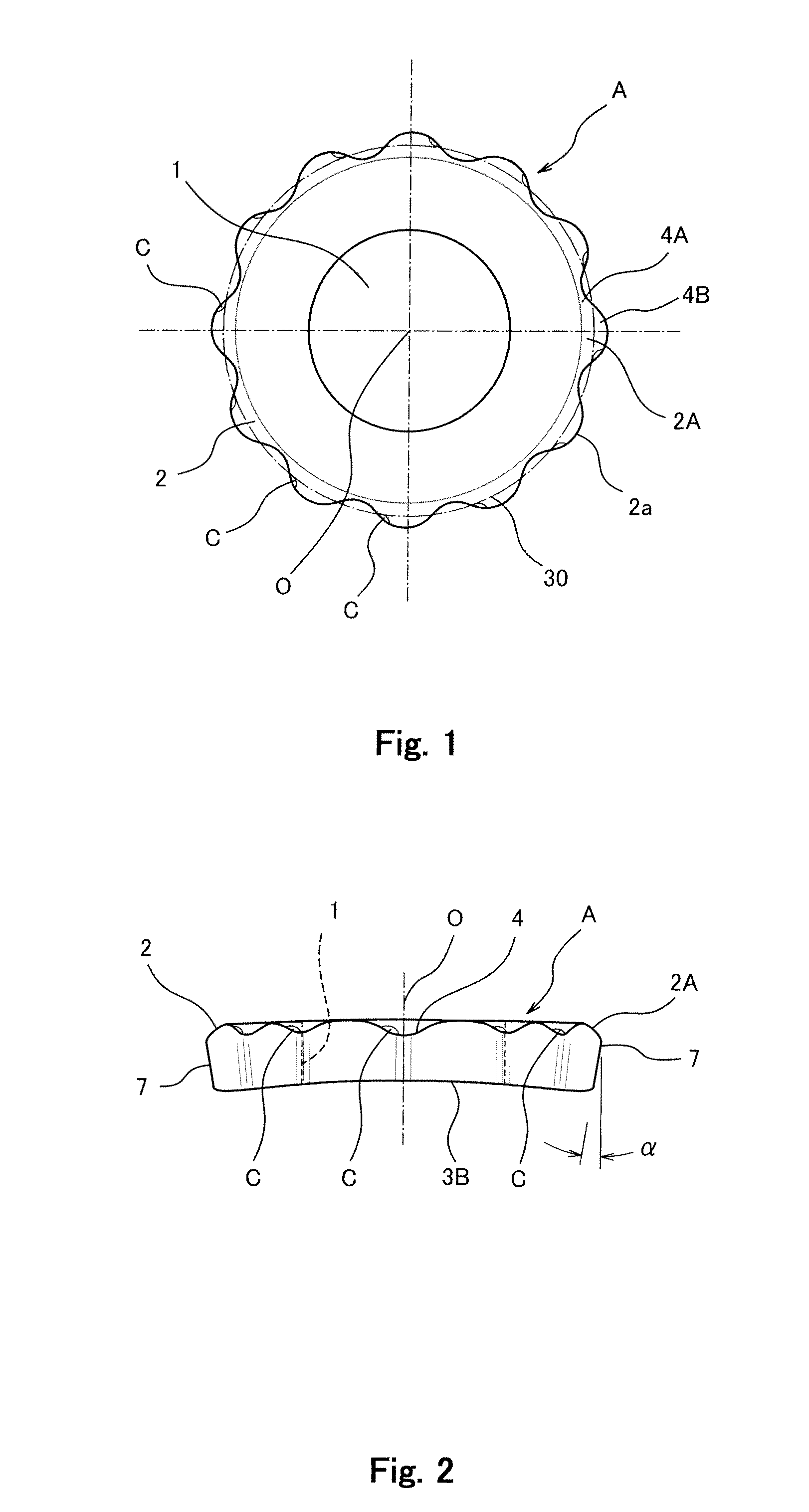
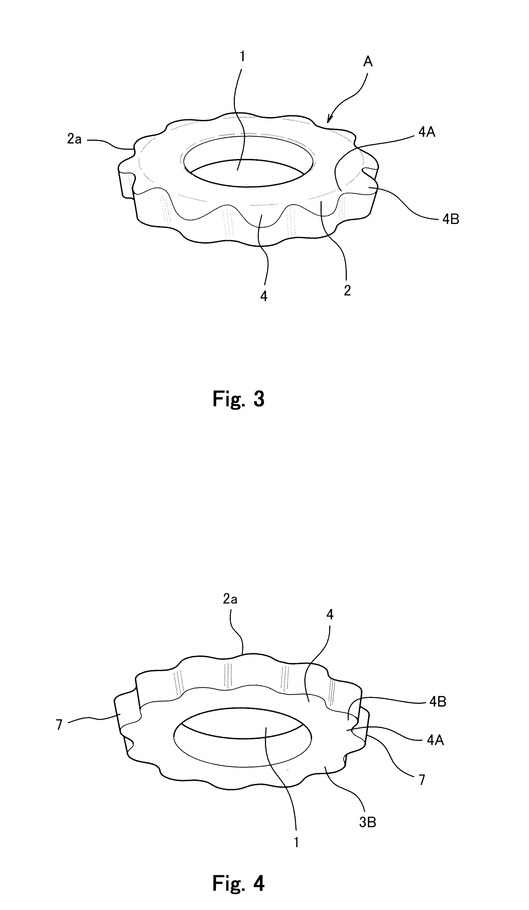
[0062]In FIG. 1, reference symbol A denotes a washer for receiving counter torque. As shown in FIG. 1, the washer A provides a through-hole 1 in a center portion thereof as seen in plan view, and a bolt shaft 15s (see FIG. 8) is inserted through the through-hole 1. The washer A provides an outer edge portion 2 which extends outwardly beyond an outer edge 10a of a nut 10 (or a bolt head 15h). Furthermore, as shown in FIG. 1, an outer periphery (outer edge) 2a of the washer A is shaped such that concave portions 4A extending inwardly and convex portions 4B extending outwardly are alternately and repeatedly provided in a radial direction around an imaginary reference circle 30 that is centered at a central point O of the washer A, as seen in plan view. The outer edge portion 2 provides engaging teeth around the washer. In this embodiment, the engaging teeth are formed on the entire outer edge portion 2. However, the engaging teeth according to the present invention are not limited...


PUM


Abstract

A fastening socket B includes an inner socket portion including engaging means for engaging a nut or the like, and an outer socket portion for engaging a washer A with an outer edge portion 2, which includes a tapered surface and engaging teeth. The tapered surface is gradually inclined outwardly and toward a bottom surface of the outer edge portion. The inner socket portion 21 and the outer socket portion 22 are coupled together with a mechanism so as to be rotated in opposite directions. The outer socket portion is provided with engaging claws for engaging the engaging teeth, and a tapered bottom end surface of each of the claws 24 is gradually inclined radially inwardly and toward a base end side. A surface of a bolt head that is brought into contact with a surface of objects is provided with frictional coefficient increasing treatment.

Description

BACKGROUND OF THE INVENTION[0001]1. Field of the Invention[0002]The present invention relates to a “fastening socket”, which is a tool for tightening a bolt or a nut of a fastener, etc. used to fasten members in steel structures, machine frames, etc., to a “washer for receiving counter torque” used for fastening, and to a preferred “fastener” for fastening using the fastening socket and the washer for receiving counter torque.[0003]2. Description of the Related Art[0004]In steel structures such as bridges, etc., a plurality of members is fastened with bolts and nuts. In recent years, “torque wrenches”, which can control rotary torque such that tensile stress acting on a bolt is at a predetermined value after the fastening is completed, are used for such fastening.[0005]An electrical powered torque wrench which is one of the torque wrenches is used (see Japanese Laid-Open Patent Application Publication No. 2008-110414). The electrical powered torque wrench (hereinafter, called an “el...

Claims


Application Information

Patent Timeline
Patent Type & Authority Patents(United States)
IPC IPC(8): B25B21/00B25B13/48F16B43/00B25B23/08F16B39/24
CPCB25B13/488B25B13/06
Inventor MIYATA, KATSUJI
Owner YUNITAITO
Why Eureka
Try Eureka