Thread-Forming Screw

a technology of threads and screws, applied in the field of threads, can solve the problems of increased torque, and difficulty, and achieve the effects of preventing slipping of the screw, easy screwing, and convenient positioning

Active Publication Date: 2008-11-27
MEDARTIS AG
View PDF12 Cites 31 Cited by
  • Summary
  • Abstract
  • Description
  • Claims
  • Application Information

AI Technical Summary

Benefits of technology

[0015]Due to the point and the at first small diameter of the preforming region, the self-drilling screw can be readily positioned and can also be screwed in very easily at the start of the screwing-in in order to prevent slipping of the screw. With the increase in the outside diameter of the preforming region, the torque to be applied also increases until the preforming region has been completely screwed in. After the preforming region has been completely screwed in, the torque to be applied increases at most to a substantially smaller extent than in conventional screws during the further screwing-in, since there is no complete contact with the bone in the intermediate region and therefore the additional friction is also lower. At the end of the screw-in operation, the anchoring region of the screw comes to lie in the cortical substance, and, since at least part of the anchoring region has an outside diameter which is the same size as or essentially the same size as the preforming region, the screw is then effectively anchored in the cortical substance.

Problems solved by technology

However, some difficulties may occur when screwing in such screws.
For example, the torque increases quite considerably with increasing screw-in depth, which in particular in the case of longer screws requires the application of quite considerable forces by the surgeon, and that in a typically very restricted operating zone.
In addition, when applying the requisite torques, which become higher and higher with increasing screw-in depth, the relatively thin screw shank may break (torsion fracture), such that the rest of the screw shank already in the bone has to be removed in a complicated manner in such a case.
To this end, however, either a further processing step is required (opening out the original core hole using a drill bit of larger diameter) or drilling is carried out immediately with a drill bit of larger diameter, there then being the risk of getting the drill bits mixed up and of not drilling with the correct drill bit.
In addition, the anchoring of the screw in the bone in the case of a larger diameter of the core hole is of course slightly poorer.
Both the additional processing step of the further pilot drilling and the risk of mix-up when selecting the drill bit and also the application of partly very high forces for producing the requisite torque are disadvantageous for surgeons.
However, it should be noted here that the core diameter cannot be selected to be as small as desired just in order to be able to screw in the intermediate region as simply as possible.
However, this is not the only conceivable field of application, and therefore the material does not absolutely have to be well-tolerated by the body.

Method used


Image

  • Thread-Forming Screw
  • Thread-Forming Screw
  • Thread-Forming Screw

Examples


Embodiment Construction

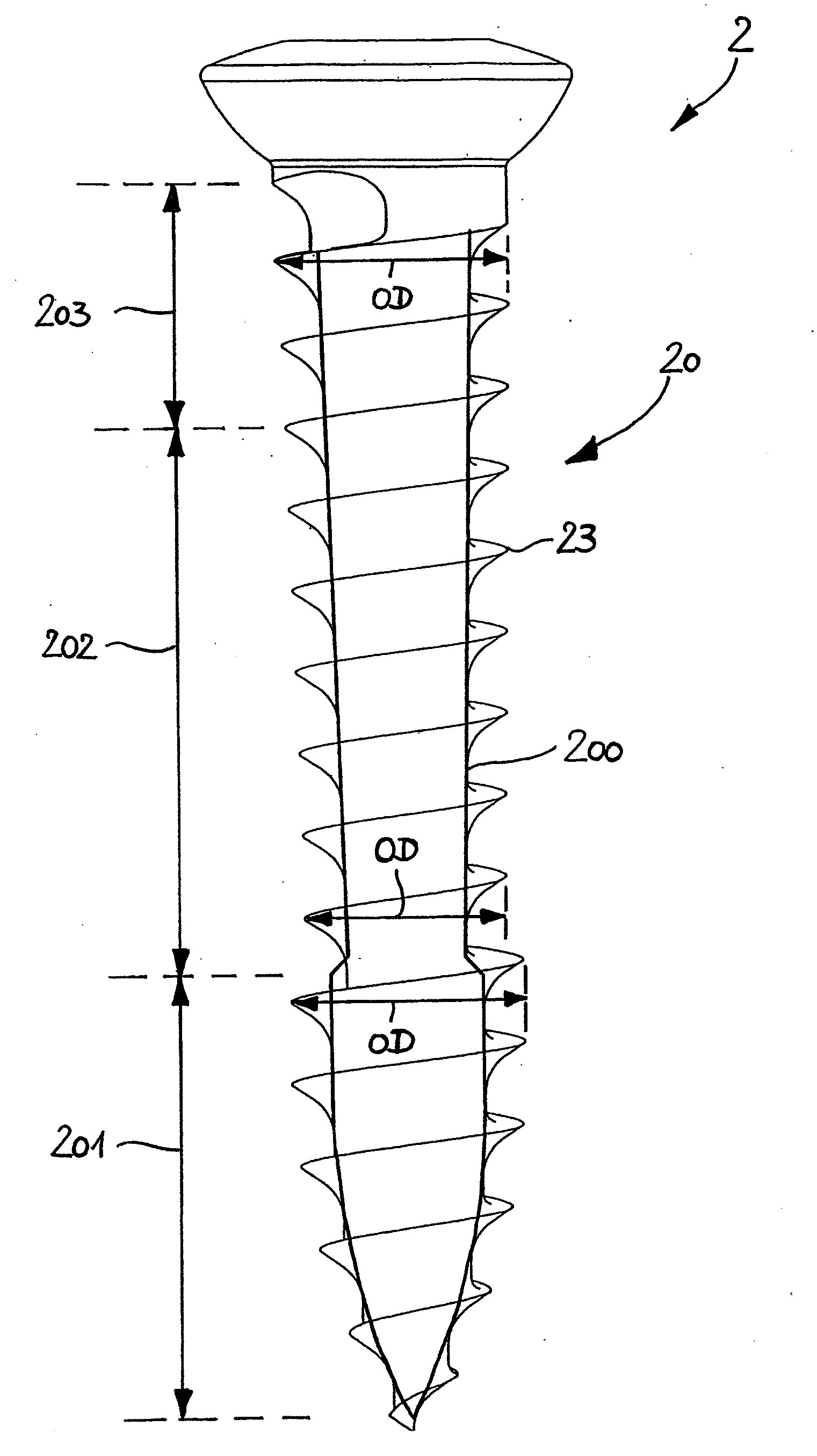
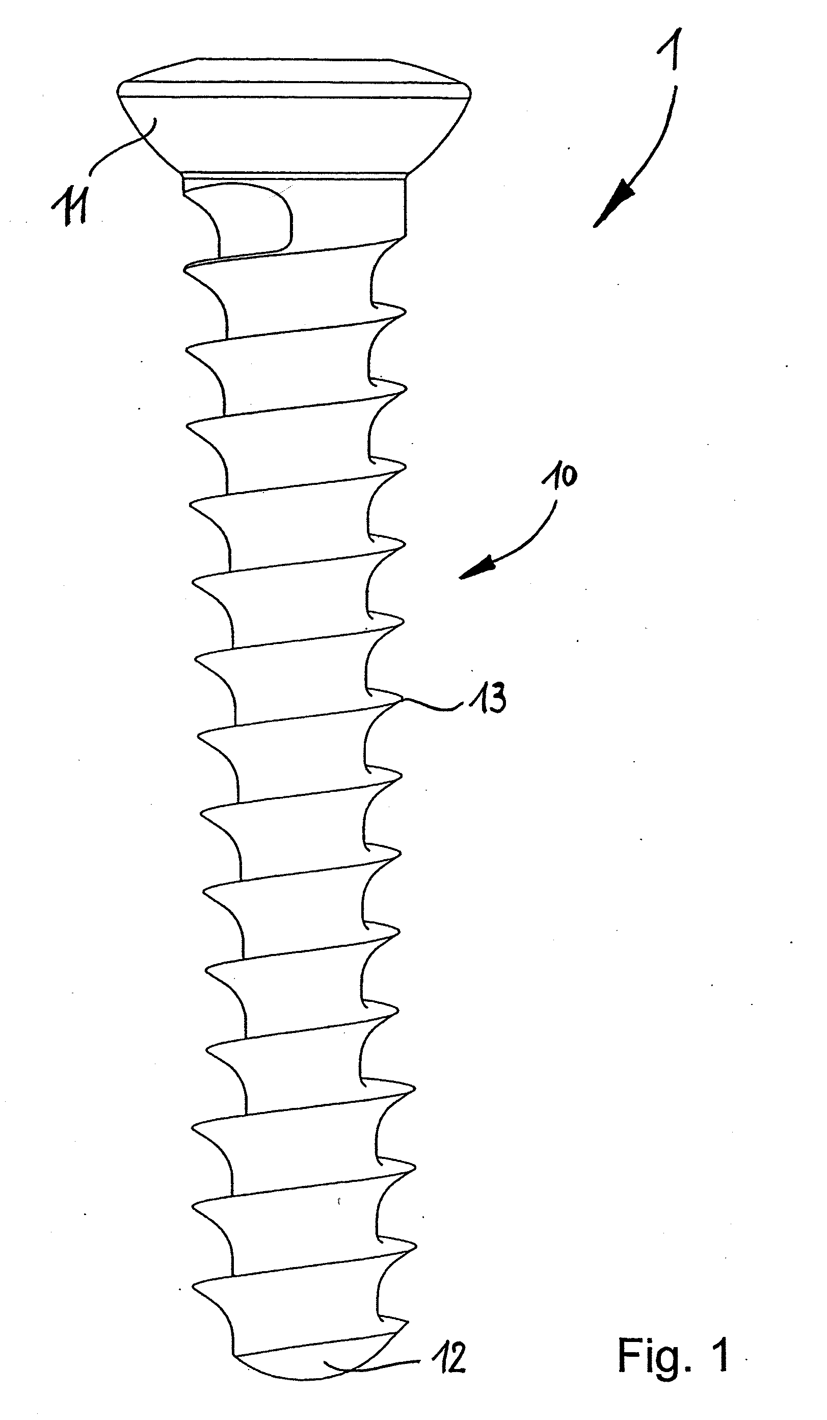
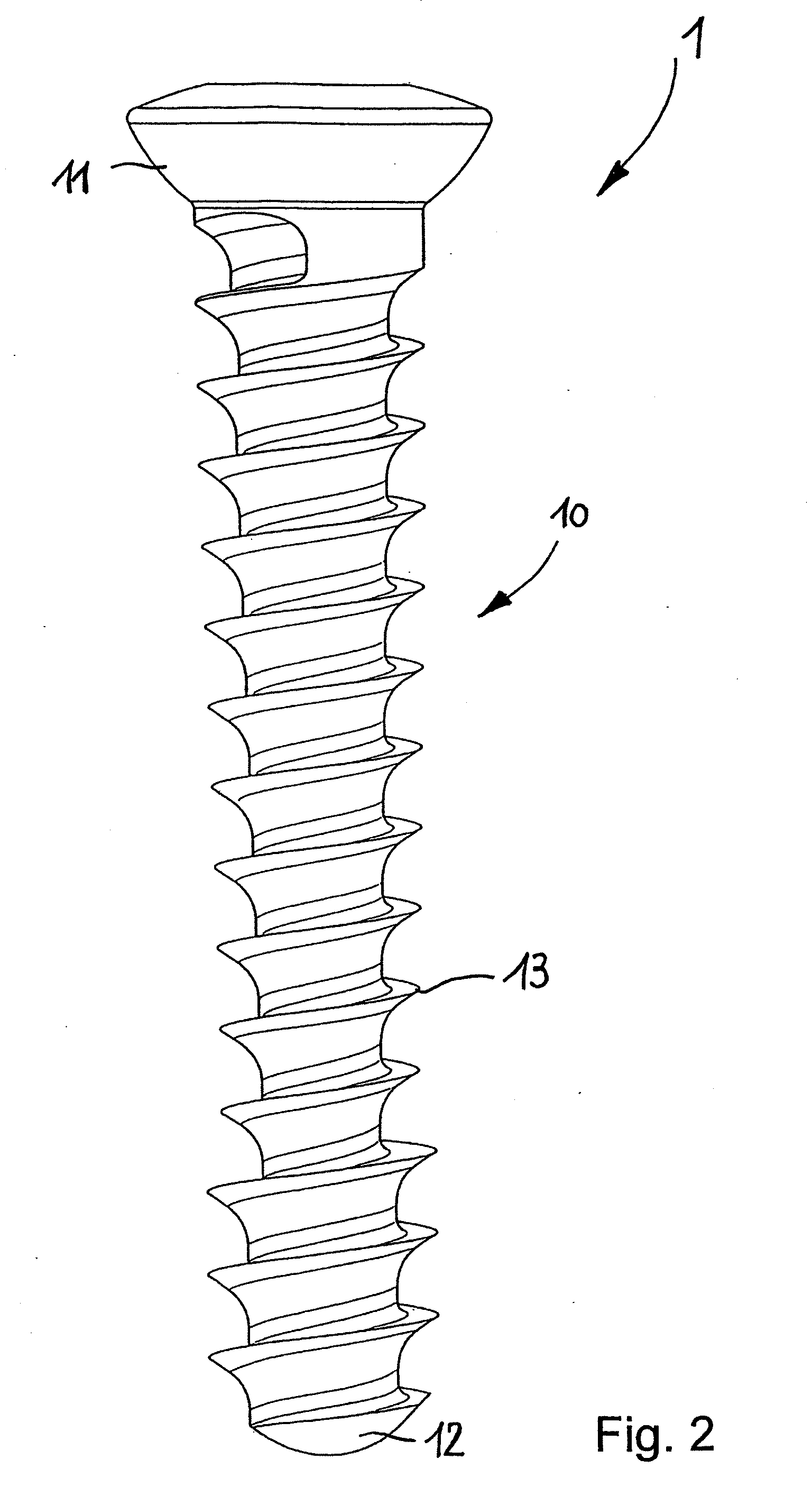
[0039]A first exemplary embodiment of the screw according to the invention is explained below with reference to FIGS. 1 to 5. FIG. 1 shows a view of the first exemplary embodiment of the screw 1 according to the invention, here a bone screw. The screw 1 comprises a shank 10 and a thread-free spherical head 11, which, for example, enables it to be accommodated in a countersunk plate hole of a bone plate (not shown). The screw end 12 is of blunt design; the screw 1 shown in FIG. 1 is therefore a self-tapping (not self-drilling) screw. FIG. 2 shows the same screw as FIG. 1, but with some additional auxiliary lines, thereby providing a better three-dimensional impression of the screw 1.

[0040]The envelope over the thread 13 of the screw, which is designed here as a continuous thread of constant pitch, can be imagined with reference to FIG. 3, although in FIG. 3 only the core 100 of the shank 10 is shown, in exaggerated representation. However, since the thread 13 has a constant radial th...


PUM


Abstract

A thread-forming screw includes a screw end, a shank, and a thread-free head, wherein the shank is provided at least partly with a thread and has a pre-forming region, an intermediate region, which is arranged to follow the pre-forming region, and an anchoring region, which is arranged so as to adjoin the intermediate region and below the head, wherein the pre-forming region is arranged so as to directly adjoin the screw end.

Description

BACKGROUND OF THE INVENTION[0001]The invention relates to a thread-forming screw, and in particular a bone screw.[0002]Thread-forming screws are widely known in the form of self-tapping or self-drilling screws. They have the advantage that no thread has to be precut. Such a screw is known, for example, from DE 20 2004 011 145 U1 and is used there as a masonry screw, for example as a brick screw. The screw described there has a preforming region with a pilot thread, adjoining which is a first thread section, then a threadless section and then at least one further thread section which is arranged below the screw thread.[0003]Self-tapping and self-drilling screws are also used in other fields, for example in medical engineering, and here in particular in the area of osteosynthesis (for example in the skull area, in the oral and maxillofacial area, in the hand area or in trauma surgery). The screws used in this case are screws whose shanks are of cylindrical or conical design over the e...

Claims


Application Information

Patent Timeline
Patent Type & Authority Applications(United States)
IPC IPC(8): F16B35/04A61B17/86
CPCA61B17/863A61B17/8625
Inventor HASENBOHLER, ALAINSCHEUBLE, PETERTHIEL, DIRK
Owner MEDARTIS AG
Why Eureka
Try Eureka