
Single-inductor multiple-output power converter

a power converter and single-inductor technology, applied in the field of single-inductor multiple-output power converters, can solve the problems of increasing the cost of switching, and reducing the cost of switching

Active Publication Date: 2010-09-16
RICHTEK TECH
View PDF2 Cites 31 Cited by
  • Summary
  • Abstract
  • Description
  • Claims
  • Application Information

AI Technical Summary

Benefits of technology

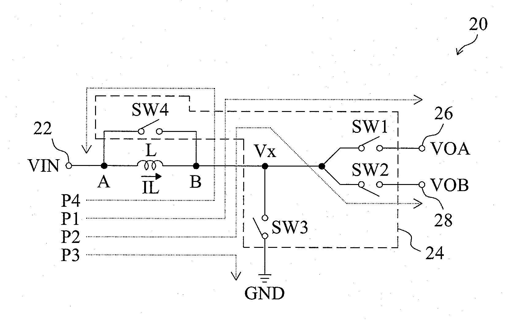
The present invention provides a power converter with fewer switches, lower cost, and improved efficiency. It includes an inductor with a single terminal connected to a power input and multiple terminals connected to power output terminals. The second terminal of the inductor is only connected to one terminal at a time, resulting in a single switch in each power path. This reduces conduction loss, switching loss, and gate drive loss, resulting in improved efficiency of the power converter.

Problems solved by technology

With technology advancement, electronic products are designed to provide more and more functions and as a result, a single power supply is barely sufficient for some electronic products.
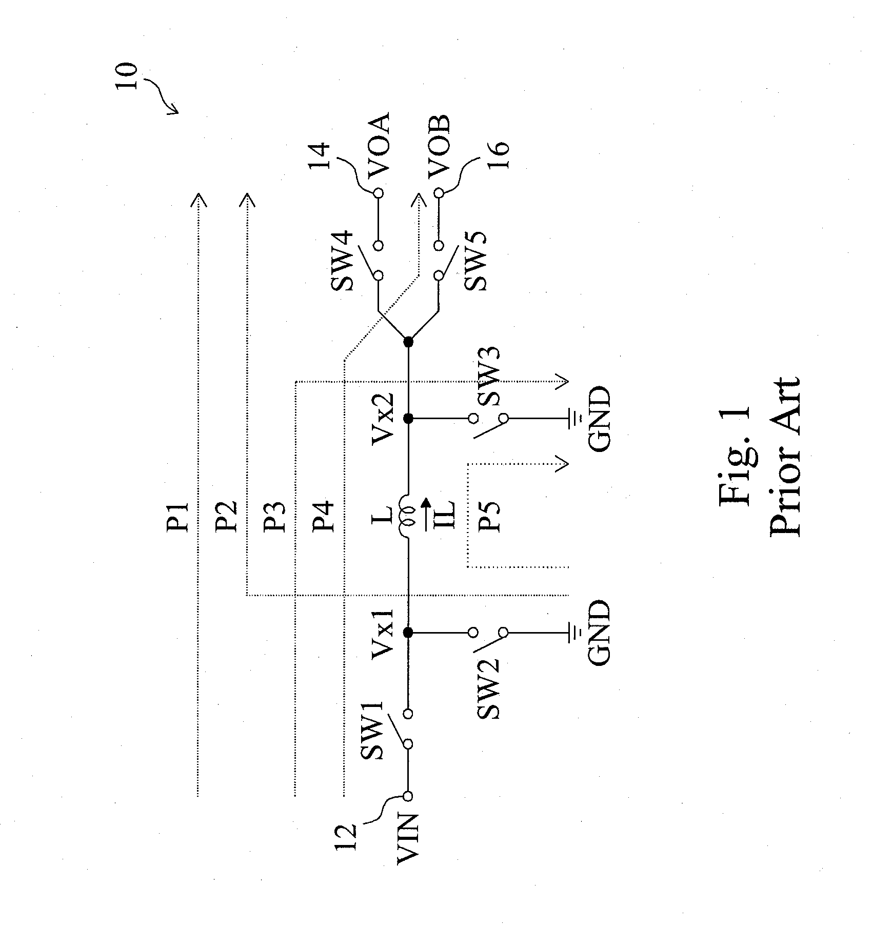
As shown in FIG. 1, the conventional SIDO power converter 10 requires five switches SW1-SW5 to generate two output voltages VOA and VOB, and each of the power paths P1-P5 has two switches for power delivery therethrough, resulting in greater conduction loss.
In addition, each switch needs a driver to drive and the switching loss and gate drive loss resulted respectively from the switches and the drivers cannot be ignored.

Method used


Image

  • Single-inductor multiple-output power converter
  • Single-inductor multiple-output power converter
  • Single-inductor multiple-output power converter

Examples


Embodiment Construction

[0019]According to the present invention, as shown in FIG. 3, a SIDO power converter 20 includes an inductor L having a first terminal A coupled to a power input terminal 22, and a switching circuit 24 operative to switch a second terminal B of the inductor L to either of the power input terminal 22, two power output terminals 26 and 28, and a ground terminal GND. The switching circuit 24 includes a switch SW1 coupled between the second terminal B and the power output terminal 26, a switch SW2 coupled between the second terminal B and the power output terminal 28, a switch SW3 coupled between the second terminal B and the ground terminal GND, and a switch SW4 coupled between the first terminal A and the second terminal B. A power path P1 is established when the second terminal B is switched to the power output terminal 26. A power path P2 is established when the second terminal B is switched to the power output terminal 28. A power path P3 is established when the second terminal B i...


PUM


Abstract

A single-inductor multiple-output power converter includes an inductor having a first terminal and a second terminal. The first terminal of the inductor is coupled to a power input terminal, and the second terminal of the inductor is switched to either of the first terminal of the inductor, multiple power output terminals, and a ground terminal. By switching the second terminal of the inductor between the first terminal of the inductor, the power output terminals, and the ground terminal, the power converter may provide multiple output voltages at the power output terminals respectively, in a less loss and thereby higher efficiency manner.

Description

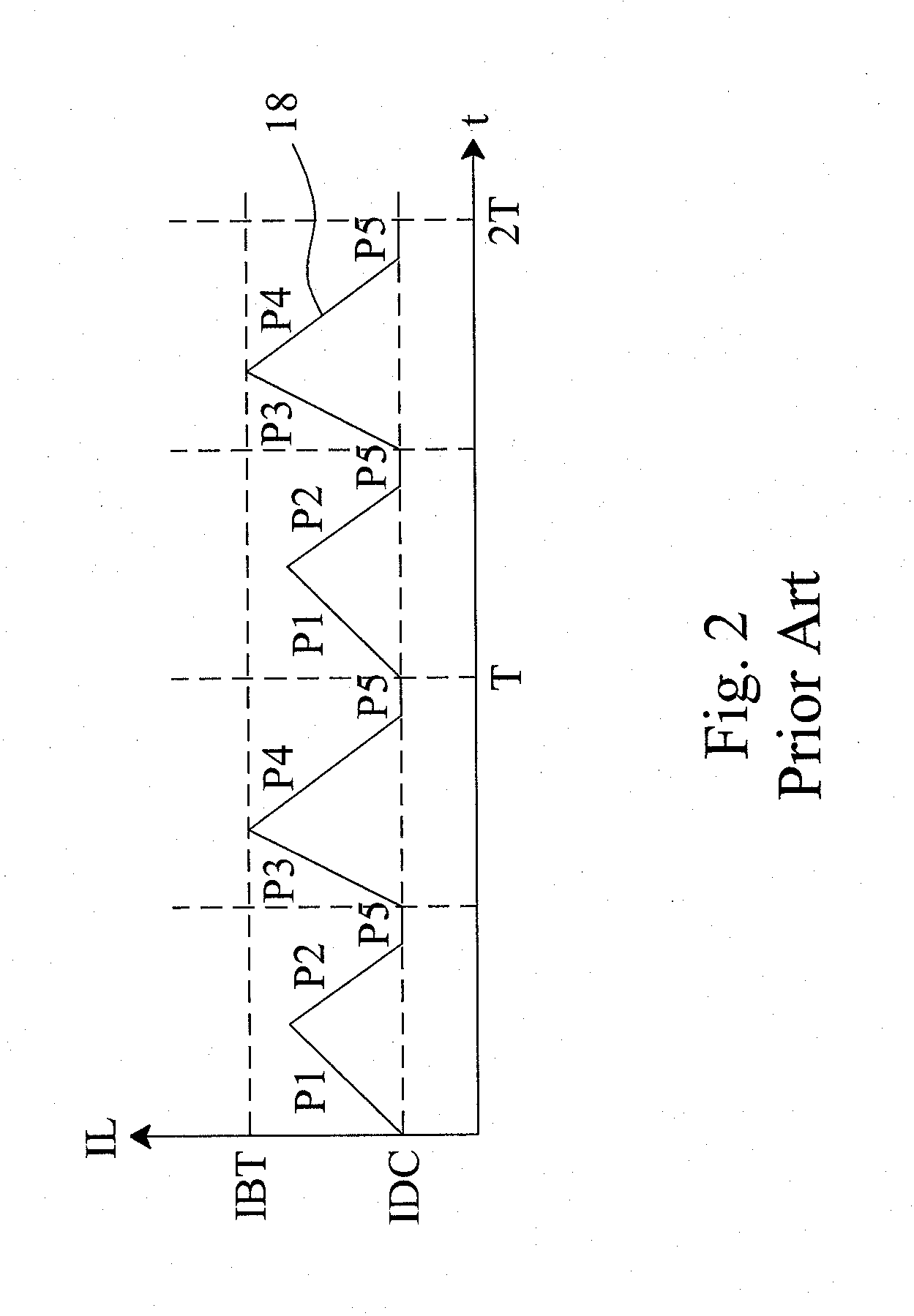
FIELD OF THE INVENTION[0001]The present invention is related generally to a power converter and, more particularly, to a single-inductor multiple-output power (SIMO) converter.BACKGROUND OF THE INVENTION[0002]With technology advancement, electronic products are designed to provide more and more functions and as a result, a single power supply is barely sufficient for some electronic products. Consequently, there is a trend for a power converter to provide multiple supply voltages. FIG. 1 is a circuit diagram of a conventional single-inductor dual-output (SIDO) power converter 10 for providing two supply voltages, which includes a switch SW1 coupled between a power input terminal 12 and an inductor L, two switches SW2 and SW3 coupled between a ground terminal GND and two terminals of the inductor L respectively, and two switches SW4 and SW5 coupled between the inductor L and two power output terminals 14 and 16 respectively.[0003]FIG. 2 is a diagram to illustrate a control method for...

Claims


Application Information

Patent Timeline
Patent Type & Authority Applications(United States)
IPC IPC(8): G05F1/10
CPCH02M2001/009H02M3/158H02M1/009
Inventor CHEN, KE-HORNGHUANG, MING-HSIN
Owner RICHTEK TECH
Learn More