Control circuit and method for a buck-boost switching converter

a control circuit and converter technology, applied in the direction of power conversion systems, dc-dc conversion, instruments, etc., can solve the problems of less effective conventional buck-boost converters, and achieve the effect of enhancing the integral efficiency of the circuit, easy setting and regulating, and switching

Inactive Publication Date: 2014-09-02
RICHTEK TECH
View PDF4 Cites 5 Cited by
  • Summary
  • Abstract
  • Description
  • Claims
  • Application Information

AI Technical Summary

Benefits of technology

[0006]Accordingly, an object of the present invention is to provide a control circuit and method with which a switching converter is capable of not only maintaining a high efficiency operation but also being set and regulated in the buck-boost mode easily for the operational modes being switched as less as possible and enhancing integral efficiency of the circuit.
[0021]From the foregoing, the control circuit and method for a buck-boost switching converter according to the present invention at least has the following advantages:
[0022]1. The control circuit and method of the present invention are capable of implementing a buck-boost switching converter with high efficiency.
[0024]3. The control circuit and method of the present invention are available for the buck-boost operation modes of the switching converter to be set and regulated easily and switched as less as possible for enhancing integral efficiency of the circuit.

Problems solved by technology

However, the conventional buck-boost converter is less effective and it is essential to promote the efficiency thereof to meet the tendency for requiring a modernized electronic device.
However, the buck-boost switching regulator of the prior reference still has deficiencies which are worth to improve substantially.

Method used


Image

  • Control circuit and method for a buck-boost switching converter
  • Control circuit and method for a buck-boost switching converter
  • Control circuit and method for a buck-boost switching converter

Examples


first embodiment

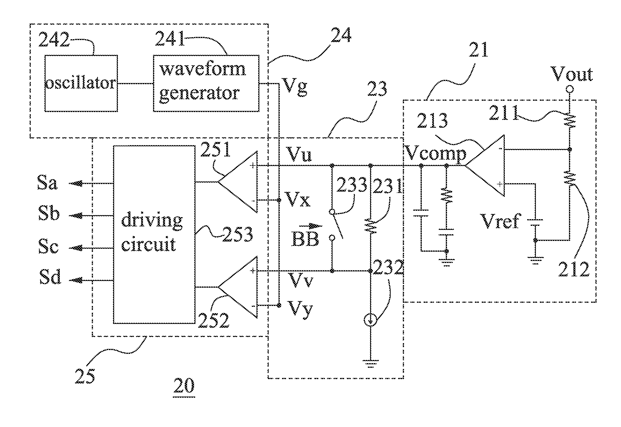
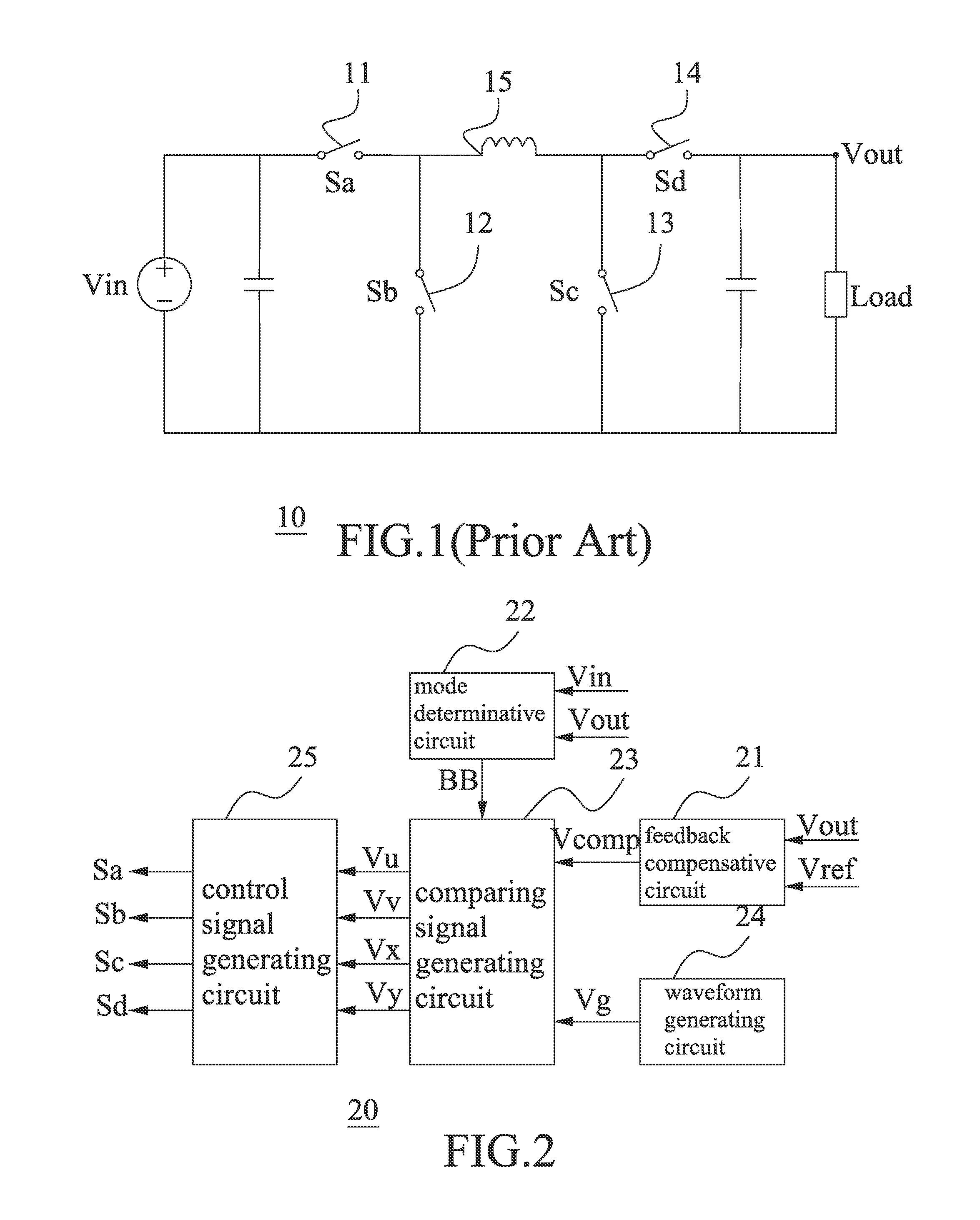
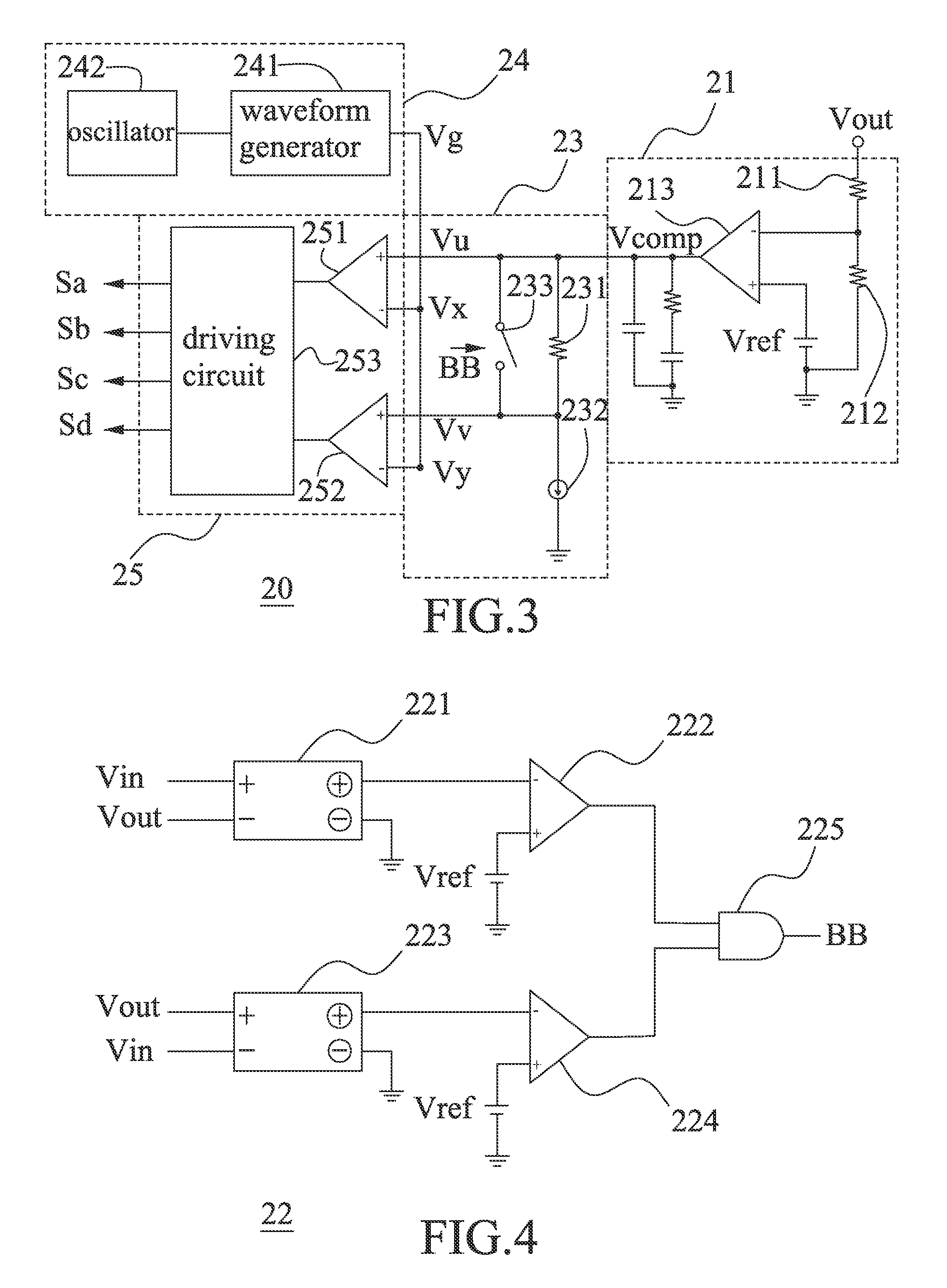
[0045]Referring to FIGS. 2, 3, and 4, the control circuit for the buck-boost switching converter according to the present invention is illustrated. The control circuit 20 comprises a feedback compensative circuit 21, a waveform generating circuit 24, a comparing signal generating circuit 23, and a control signal generating circuit 25. Besides, the comparing signal generating circuit 23 is controlled with a buck-boost operation mode signal BB generated by a mode determinative circuit 22, and the principle of the operation thereof will be recited in details afterward with reference to FIGS. 5, 6 and 7.

[0046]The feedback compensative circuit 21 in FIG. 3 includes an amplifier 213, and resisters 211, 212. The amplifier 213 has an output end, a negative input end, and a positive input end connected to an output reference voltage Vref; the resister 211 is connected to the output end of the buck-boost switching converter 10 shown in FIG. 1 and the negative input end of the amplifier 213 re...

second embodiment

[0056]Referring to FIG. 8, the control circuit of the buck-boost switching converter according to the present invention is illustrated. The control circuit for the buck-boost switching converter 70 in the present embodiment comprises a feedback compensative circuit 21, a waveform generating circuit 24, a comparing signal generating circuit 73, and a control signal generating circuit 25. Besides, a switch 733 of the comparing signal generating circuit 73 is controlled to be turned on or off with a buck-boost operation mode signal BB generated by the mode determinative circuit 22 shown in FIG. FIG. 4, and the principle of the operation thereof will be recited in details afterward with reference to FIGS. 9, 10 and 11.

[0057]The feedback compensative circuit 21, the waveform generating circuit 24, and the control signal generating circuit 25 shown in FIG. 8 and FIG. 3 are identical, and no details for the preceding circuits 21, 24 and 25 will be described further. In the present embodime...

third embodiment

[0061]Referring to FIG. 12, the control circuit of the buck-boost switching converter according to the present invention is illustrated. The control circuit for the buck-boost switching converter 80 in the present embodiment comprises a feedback compensative circuit 21, waveform generating circuits 24, 84, a comparing signal generating circuit 83, and a control signal generating circuit 25. Besides, switches 831, 833 of the comparing signal generating circuit 83 is controlled to be turned on or off with a buck-boost operation mode signal BB generated by the mode determinative circuit 22 shown in FIG. 4.

[0062]The feedback compensative circuit 21, the waveform generating circuit 24, and the control signal generating circuit 25 shown in FIG. 12 and FIG. 3 are identical, and no details for the preceding circuits 21, 24 and 25 will be described further. An oscillator 842 and a waveform generator 841 included in a waveform generating circuit 84 are similar to the oscillator 242 and the wa...


PUM


Abstract

A control circuit and method for a buck-boost switching converter provides a mode determinative circuit to judge the timing of an operation under buck-boost mode based on the input voltage, the output voltage and the mode reference voltage; meanwhile, the control signal generating circuit is provided to turn off the second switch during the first switch being on, turn on the second switch during the first switch being off, turn off the fourth switch during the third switch being on, turn on the fourth switch during the third switch being off, wherein the duty cycles of the first and third switches are identical, and duty cycles of the second and fourth switches are identical.

Description

BACKGROUND OF THE INVENTION[0001]1. Field of the Invention[0002]The present invention is related to a buck-boost switching converter, and particularly to a highly efficient control circuit and method for a buck-boost switching converter.[0003]2. Brief Description of the Related Art[0004]In order to maintain an electronic device installed with batteries to provide a steady input power source, usually the buck-boost converter is utilized to regulate the power source. However, the conventional buck-boost converter is less effective and it is essential to promote the efficiency thereof to meet the tendency for requiring a modernized electronic device.[0005]U.S. Pat. No. 6,166,527 entitled “CONTROL CIRCUIT AND METHOD FOR MAINTAINING HIGH EFFICIENCY IN A BUCK-BOOST SWITCHING REGULATOR” proposes that the switching regulator can be operated in a buck mode in case of the input voltage being higher, in a buck-boost mode in case of the input voltage approaching the standard output voltage, and...

Claims


Application Information

Patent Timeline
Patent Type & Authority Patents(United States)
IPC IPC(8): G05F3/16H02M3/158
CPCH02M3/1582
Inventor CHEN, WEN-WEILIU, KUO-CHI
Owner RICHTEK TECH
Why Eureka
Try Eureka