Simplified lighting control system

a lighting control system and simplified technology, applied in the field of lighting control, can solve the problems of wide cost-effective gap, complex requirements, and many applications that cannot justify, afford, or truly require such complexity either for the initial cost or the maintenance cost, and achieve the effects of simple installation, simplified power switching control, and convenient us

Active Publication Date: 2012-04-03
LITECONTROL
View PDF4 Cites 5 Cited by
  • Summary
  • Abstract
  • Description
  • Claims
  • Application Information

AI Technical Summary

Benefits of technology

[0008]The invention provides a means for the simplified power switching control (i.e., using direct AC line voltage or direct current (DC) power switches instead of low voltage switches that control higher-current-capable relays) of the power supplies that drive the light producing devices in an plurality of luminaires or lighting fixtures in a given installation. The lighting control system facilitates multiple modes of lighting configurations while requiring fewer switches than the prior art and also being easier to operate. The system supports the simultaneous use of multiple lighting technologies. Other embodiments showing extensions to the invention are also disclosed.

Problems solved by technology

While it may be desirable to have a complex system or even a sophisticated computer or controller-based lighting control system, many applications simply cannot justify, afford, or truly require such complexity either for the initial cost or for maintenance costs, especially when budgets are under increasing scrutiny.
This leaves a wide gap for cost effective, simpler solutions.

Method used


Image

  • Simplified lighting control system
  • Simplified lighting control system
  • Simplified lighting control system

Examples


first embodiment

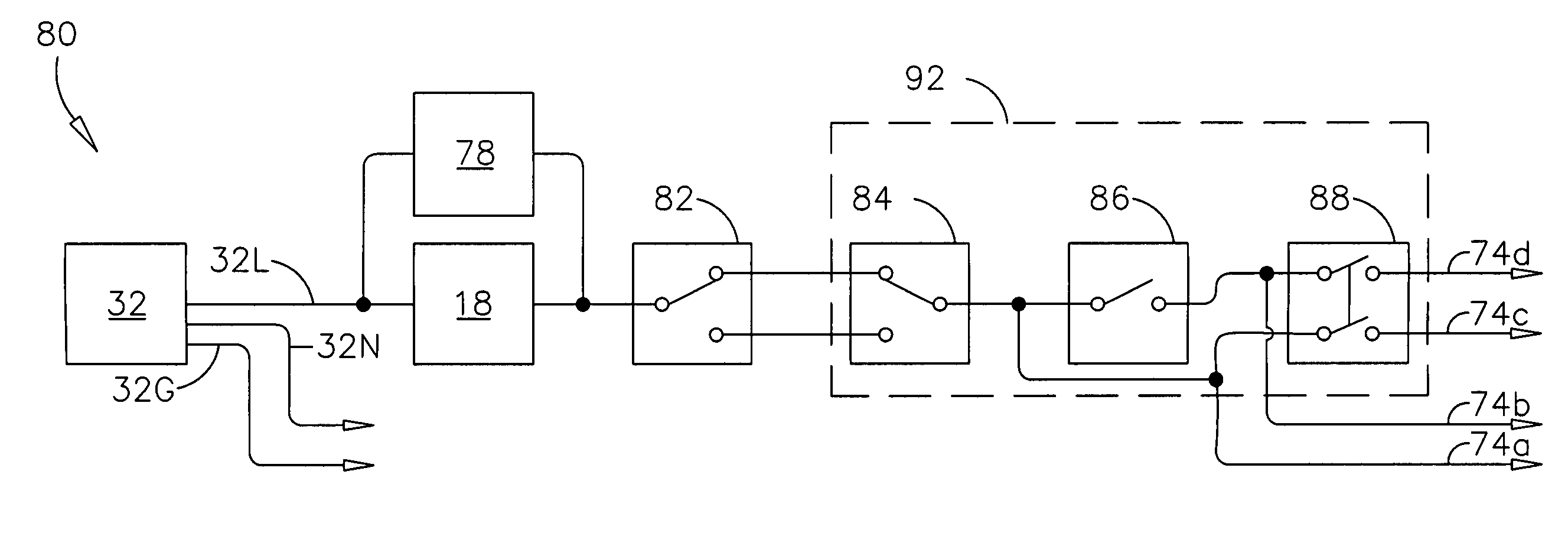
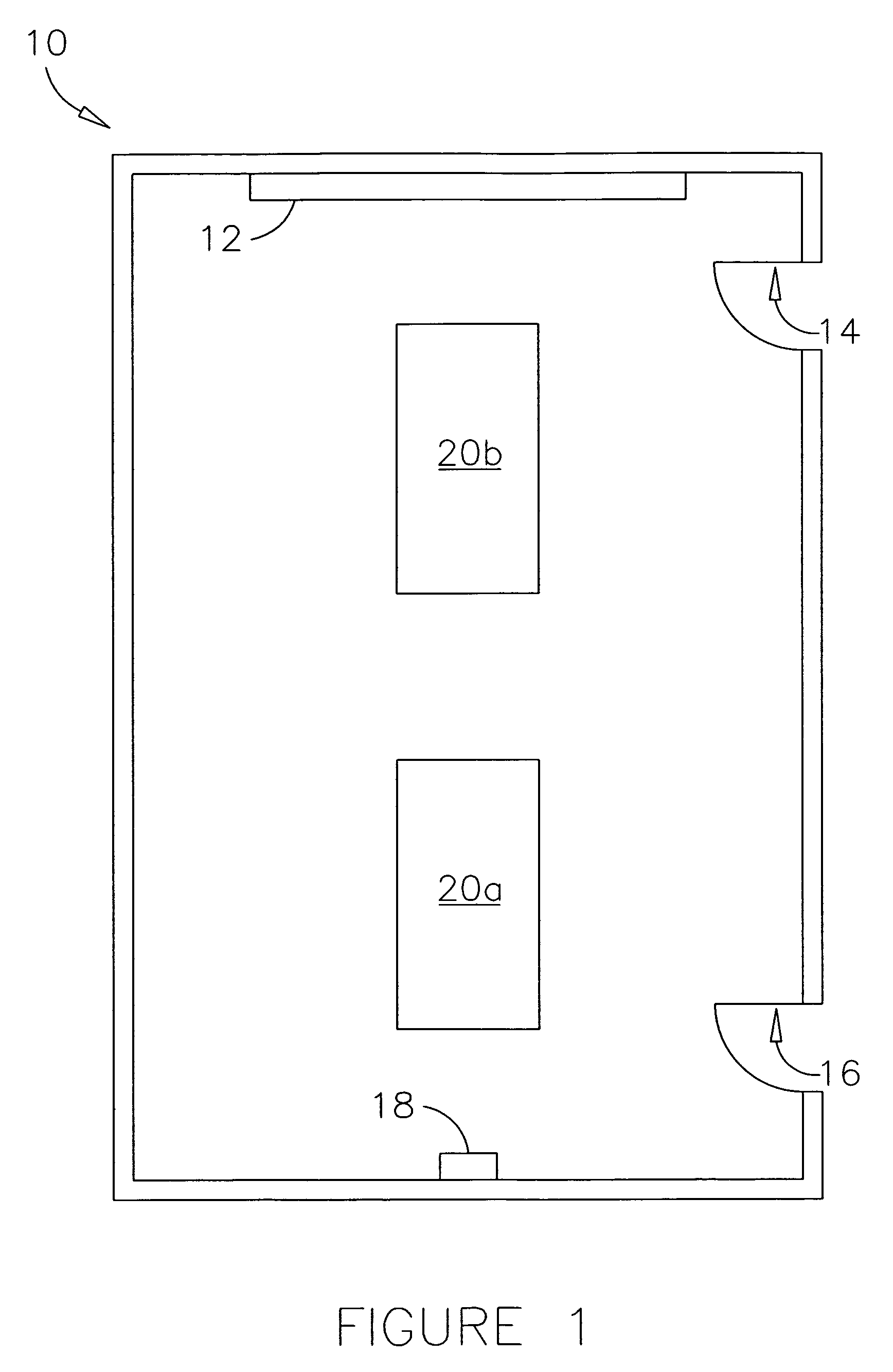
[0043]Referring now to FIGS. 1, 2 and 5, all in accordance with the present invention, there is shown a control system 50 used to control the lighting in a room 10. System 50 comprises an AC power source 32 having three connections: line 32L, neutral 32N, and ground 32G; switches 52 and 54; and luminaires 20a and 20b. Switches 52 and 54 are typically located in a two-switch control station 48 or switch grouping near either entrance 14 or 16 of room 10. Switch 52 is of a single pole, double throw, center off configuration and combines the functions of two switches by acting as both a master on / off and higher / lower light level switch, unless system 50 had some other external means (not shown) of controlling the power to luminaires 20a and 20b. Switch 52 can also be of a single pole, triple throw configuration, which would not require “off” being located in the center position, although this configuration is less common.

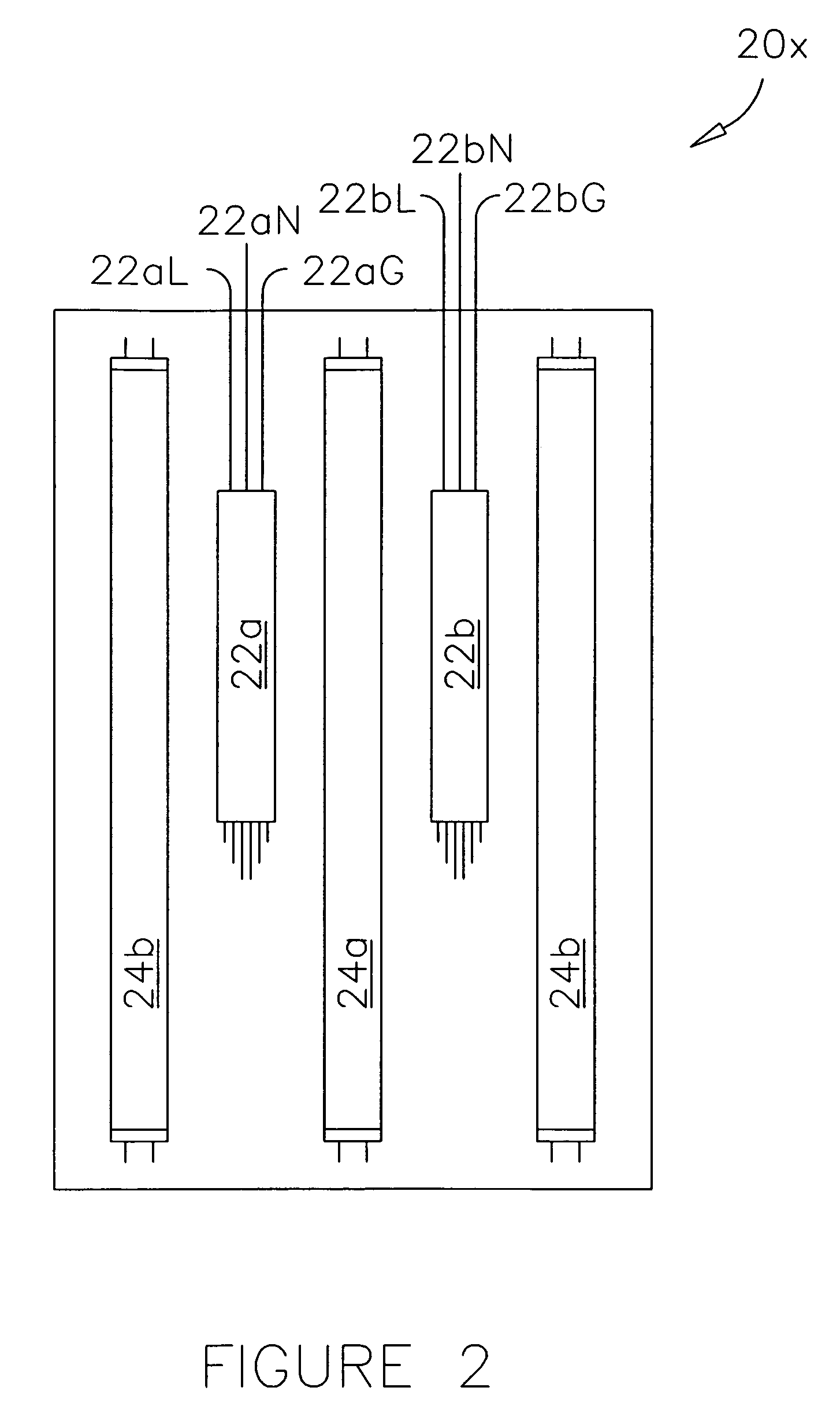
[0044]Ballasts 22a and 22b neutral wires 22aN and 22bN connect to ...

second embodiment

[0046]Referring now to FIGS. 1, 2 and 6, all in accordance with the present invention, there is shown a lighting control system 60 used to control the lighting in a room. System 60 comprises an AC power source 32 having three connections: line 32L, neutral 32N and ground 32G, switches 62, 64 and 66; and luminaires 20a and 20b. Master on / off switch 62 and higher / lower light level switch 64 and switch 66 are typically located in a three-switch control station 58 or switch grouping near either entrance 14 or 16 of room 10. Switch 62 acts as the master on / off unless system 60 had some other external means (not shown) of controlling the power to luminaires 20a and 20b. Switch 62 is of a SPST configuration, switch 64 is of a SPDT configuration, and switch 66 is of a DPST configuration. The prior art approach, as shown in FIG. 4, requires at least two additional switches to accomplish the same tasks.

[0047]Ballasts 22a and 22b neutral wires 22aN and 22bN connect to power source neutral 32N,...


PUM


Abstract

The invention offers an improvement in lighting control systems by providing a simplified power switching control system (i.e., using direct AC line voltage or DC current power switches instead of low voltage switches that control higher-current-capable relays) that controls the power to the power supplies that drive the light producing devices in a plurality of luminaires or lighting fixtures in a given installation. The lighting control system facilitates multiple modes of lighting configurations while requiring fewer switches that the prior art and also being easier to operate. The system supports the simultaneous use of multiple lighting technologies. Other embodiments showing extensions to the invention are also disclosed.

Description

FIELD OF THE INVENTION[0001]The present invention relates to the control of lighting and more particularly, to the cost-effective control of a plurality of light sources for use in lighting fixtures / luminaires as well as standalone devices commonly used in lighting applications.BACKGROUND OF THE INVENTION[0002]The control of light and in particular artificial light is important for many reasons including ergonomic and ecological ones as well as energy and cost savings. Different approaches and control systems have been around for many years. A control system can be as simple as a single alternating current (AC) general purpose snap switch or as complex as centralized or decentralized overall energy management system. Complex integrated building management systems have their place by being able to offer advanced features such as internet and wireless access, utility interface for load shedding, messaging to issue maintenance alerts, and secure two-way communication to each device usi...

Claims


Application Information

Patent Timeline
Patent Type & Authority Patents(United States)
IPC IPC(8): H01H19/64
CPCH05B37/0209H05B47/10H05B47/17
Inventor HAHNLEN, BRIAN D.YON, JEREMY W.
Owner LITECONTROL
Why Eureka
Try Eureka