Reagent container

a technology for reagents and containers, applied in the field of reagent containers, can solve the problems of time and effort, difficult to closely pack a plurality of reagent holding sections in one reagent container, and difficult to downsize the reagent container, so as to prevent measurement results and reduce the amount of for

Active Publication Date: 2010-09-16
FUJIFILM CORP +1
View PDF7 Cites 26 Cited by
  • Summary
  • Abstract
  • Description
  • Claims
  • Application Information

AI Technical Summary

Benefits of technology

[0026]The reagent container of the present invention includes a container body with an opening of each of the holding sections sealed with at least one sheet-like seal member and a lid having a plurality of hollow piercing sections formed on a lower surface thereof to protrude downward and openings formed in an upper surface thereof to allow the probe to be inserted therethrough or withdrawn therefrom, and the container is configured such that the seal member is pierced by pressing the lid onto the container body from above and the probe is allowed to be inserted into the holding sections through the hollow sections of the piercing sections. Therefore, reagent container of the present invention has the following advantageous effects. That is, normally, the openings of the container body are only sealed with the seal member so that it is not bulky and the container body is simply covered with the lid, and so that the reagent container can be made small even if it has a plurality of holding sections. Further, piercing of the container body can be made at a time by simply pressing the lid onto the container body, so that the piercing of the container body is extremely easy. Further, the hollow piercing sections secure the passage of the probe so that the probe does not require a specific strength and a required thinness may be ensured, and contamination of a portion of the probe other than the tip thereof may be prevented. Still further, this ensures accurate liquid level detection even by a capacitive method.
[0027]When the reagents include a plurality of types of reagents and each of the holding sections is configured to hold an amount of each corresponding reagent according to a required amount thereof, the reagent container may be made small in which the plurality of types of reagents is held in a balanced manner according to the required amount of each type of reagent.
[0028]Further, when at least one of the openings of the plurality of holding sections has a size different from the size of the rest of the openings and each of the piercing sections has the same outer dimension, the force required for each piercing section for performing piercing becomes substantially uniform, whereby the piercing may be performed stably.
[0029]Still further, when the seal member is made of a material that adheres tightly to the piercing sections of the lid after pierced, the reagents are shut off from the external environment so that leakage of the reagents may be prevented and a quality change or a concentration change due to evaporation in the reagents may be prevented, whereby measurement results are prevented from being affected by such changes.
[0030]Further, when the seal member is made of a material that does not produce a fragment separated from the seal member when piercing is performed by the piercing sections, dropping of a fragment of the seal member into a holding section is prevented and the probe is prevented from being adversely affected by the fragment dropped in the holding section.
[0031]Preferably, the seal member is a member that allows a hole having a shape identical to the cross-section of the outer circumference of the piercing section to be formed.

Problems solved by technology

In the typical reagent container having a screw cap described above, the cap size is greater than the opening size of the reagent container so that it has been difficult to closely pack a plurality of reagent holding sections in one reagent container.
Further, even when the amount of a reagent to be held is very small, it has been difficult to downsize the reagent container because of a limitation in downsizing the cap.
Further, it has been necessary to individually open the caps one by one, requiring the time and effort if there are many caps to be opened.
Still further, it has been difficult for a reagent container holding a plurality of types of reagents to hold the reagents in a balanced manner in which, depending on the type of reagents, volume of reagent decreases when required amount is small and volume of reagent increases when required amount is large.
It is difficult, however, to expect the pipette to have a sufficient strength to pierce the cap because the pipette is used for accurately handling a minuscule amount of a liquid reagent and therefore needs to be as thin as possible in order to reduce the adherence of the reagent other than the amount to be sucked.
The adherence of the liquid to the cap may lead to an erroneous detection of the liquid level of the reagent when detected by a capacitance measurement.
That is, there may be a case in which the pipette would have been erroneously judged to reach the liquid level when the pipette contacted the liquid around the hole, causing it difficult to perform accurate liquid level detection repeatedly.
Further, the reagent adheres to a portion of the pipette other than the tip when the pipette passes through the pierced hole of the cap adhered with the liquid, whereby the pipette is contaminated with the reagent to an upper portion of the tip that actually contacts the liquid level of the reagent.
Generally, the tip of a pipette is cleaned with water or the like each time the sucking is performed to reduce the residual amount of the reagent to a predetermined amount, if a larger pipette portion contacts the liquid, the more area needs to be cleaned, posing a problem that more time and effort is required for the maintenance.
In the reagent container disclosed in Japanese Unexamined Patent Publication No. 2004-156971, it is difficult to closely pack a plurality of reagent holding sections in one reagent container because the container needs to be provided with a bulky hinge mechanism.
In addition, a mechanism for opening / closing the hinge mechanism needs to be provided in the analyzing device, resulting in that the analyzing device becomes complicated in structure and expensive.

Method used


Image

  • Reagent container
  • Reagent container
  • Reagent container

Examples


second embodiment

[0078]Next, the features of the second embodiment will be further described with reference also to FIG. 5. FIG. 5 is a perspective view in which reagent container 300 is disposed in a reagent container mounting area 350 of an analyzing device (not shown). Container body 302 of reagent container 300 has two upward engaging recesses 357 formed on outer circumferential wall 356. Lid 304 has downward engaging protrusions (engaging section) 360 formed at positions corresponding to engaging recesses 357 to engage with and held by engaging recesses 357. This allows integrated reagent container 300 to be formed by pressing lid 304 onto container body 302 and causing them to engage with each other. Horizontally protruding tabs (positioning section) 362 and 363 (FIG. 4A) are formed on the wall surfaces of cover wall 382 of lid 304 oppositely separated from each other in a longitudinal direction of cover wall 382. Tab 362 has a hole 362a formed in the center (FIG. 4A).

[0079]In the mean time, r...

first embodiment

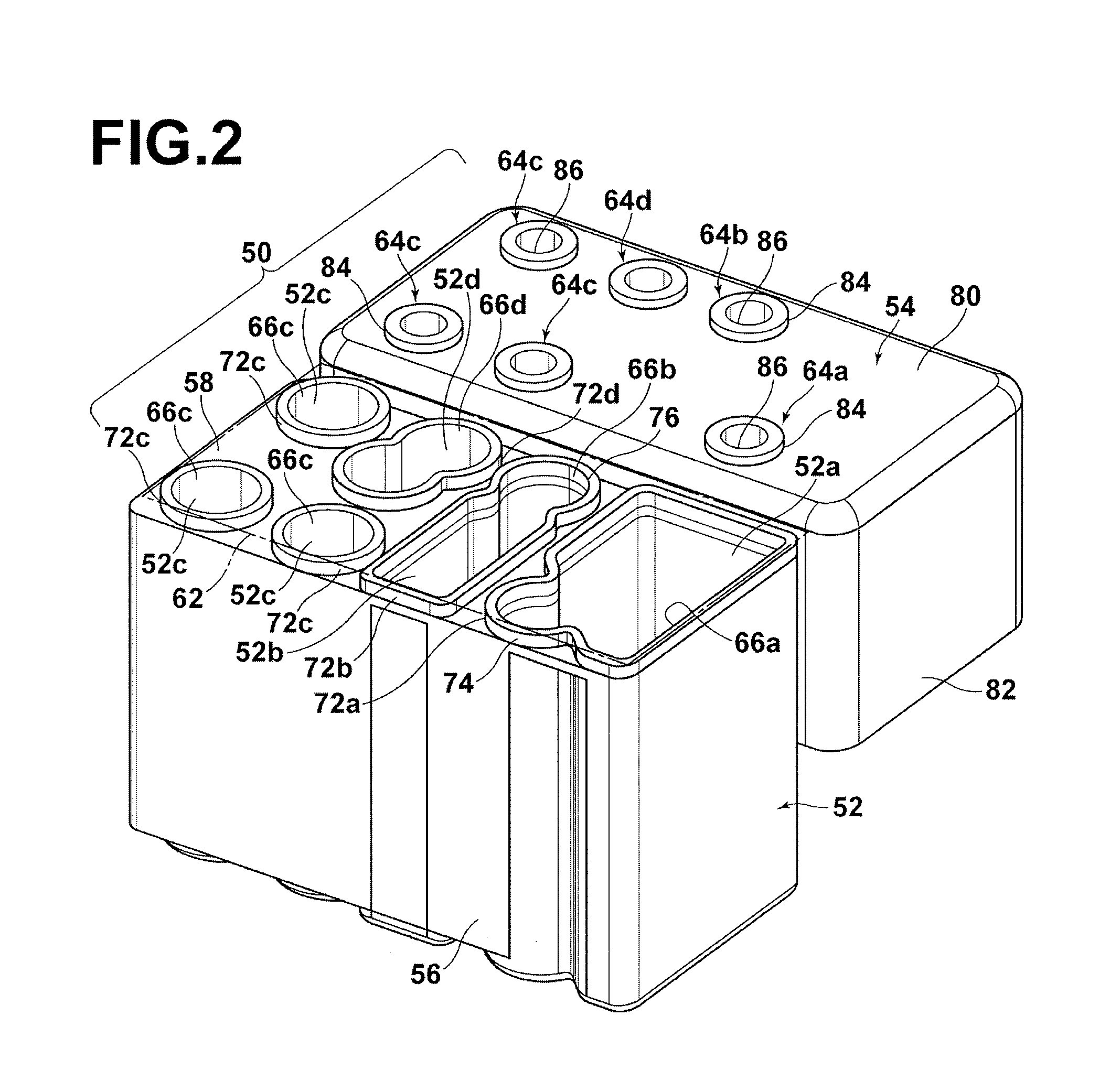
[0082]As in the first embodiment, when using lid 54′, lid 54′ is put on container body 52′ from above and simply pressed downward. Then, reagent container 50′ can be carried around by pinching the handle so that reagent container 50′ may be mounted easily in an analyzing device or the like. When lid 54′ is provided with handle 60 as in the present modification, rectangular engaging opening (engaging section) 70a is provided in cover wall 82′ and engaging protrusion 70b that makes concavo-convex engagement with engaging opening 70a is provided on container body 52′ so that container body 52′ is securely held by lid 54′. A pair of engaging opening 70a and engaging protrusion 70b is provided at each of opposite positions of cover wall 82′. But the shapes and attaching positions of engaging opening 70a and engaging protrusion 70b are not limited to those described in the first modification, and modifications and changes may be made. It should also be appreciated that the shape, size (le...

third embodiment

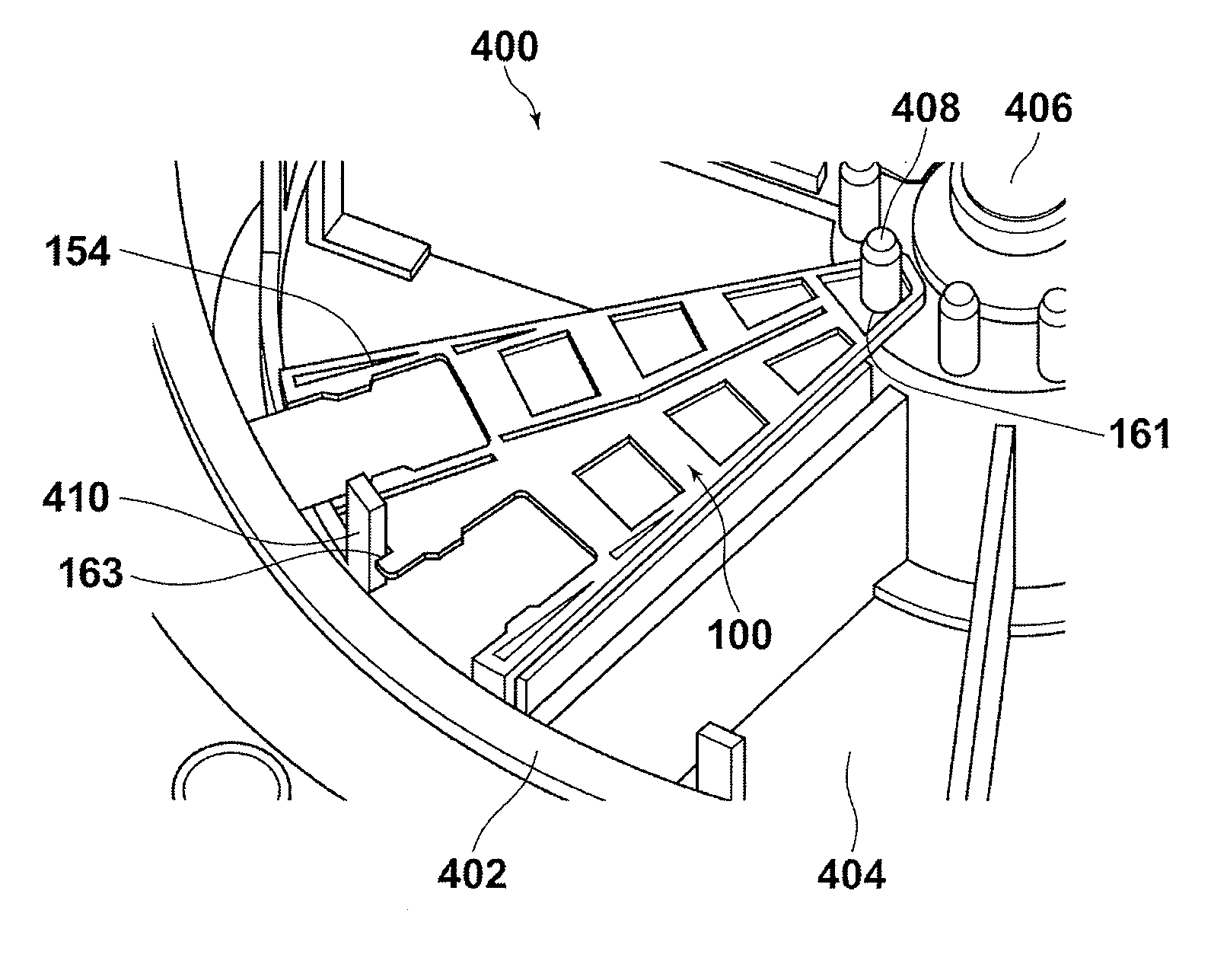
[0084]Next, reagent container 100 according to the present invention will be described with reference to FIGS. 7 and 8. FIG. 7 is an overall perspective view of reagent container 100. FIG. 8 is a perspective view of container body 102 of reagent container 100. Container body 102 has a fan shape in planar view and a rectangular shape in side view. Such shape is appropriate for mounting reagent containers 100 in an analyzing device side by side in a circle with the narrower portion of the fan shape of each reagent container 100 being oriented on the inner side. For the sake of convenience for explanation, hereinafter, the narrower portion is referred to as “first end” and the arc shaped wider side is referred to as “second end”.

[0085]As shown in FIG. 8, container body 102 includes a plurality of holding sections 152a, 152b, 152c, and 152d having openings (opening sections) 166 (166a, 166b, 166c, and 166d) in top wall 158. Holding sections 152a, 152b, 152c, and 152d are integrally form...


PUM


Abstract

A reagent container having a plurality of open holding sections, each holding a reagent and into which a probe is inserted to suck the reagent. An opening of each of the holding sections is sealed with at least one sheet-like seal member. The reagent container includes a container body and a lid having a plurality of hollow piercing sections, formed on a lower surface of the lid, protruding downward for piercing the seal member at each of the openings, and openings, formed in an upper surface of the lid, communicating with piercing sections respectively to allow the probe to be inserted therethrough or withdrawn therefrom.

Description

TECHNICAL FIELD[0001]The present invention generally relates to a reagent container for use with an automatic analyzing device for analyzing, for example, a blood sample or the like, and more particularly to a reagent container for use with an automatic analyzing device that uses a dispensing probe (hereinafter, simply referred to as “probe”) for sucking a small amount of a reagent from a reagent container and dispensing the reagent on a microchip or the like.BACKGROUND ART[0002]Microchips having a micro-channel are beginning to be used for automatic analyzing devices that analyze blood samples, urine samples, and the like. In such a microchip, a reagent, including a buffer (buffer fluid), is injected in a micro-channel by a probe and then a high voltage is applied to the micro-channel. The application of the high voltage causes each composition component of the sample in the channel to be migrated, and a target substance for measurement in the sample is separated by the difference ...

Claims


Application Information

Patent Timeline
Patent Type & Authority Applications(United States)
IPC IPC(8): B01L3/00
CPCG01N35/026G01N35/1002G01N35/1079B01L3/523B01L2200/16B01L2200/026B01L2300/044B01L2300/0672B01L2300/0861B01L3/527G01N2035/0436
Inventor DENAWA, TATSUYUKIHAYASHI, MASAYOSHIKUROSAWA, TATSUOSATOMURA, MASAHIROWATANABE, MITSUO
Owner FUJIFILM CORP
Why Eureka
Try Eureka