Prosthetic Valve Delivery System

a technology of prosthetic valves and delivery systems, applied in medical science, multi-lumen catheters, balloon catheters, etc., can solve the problems of inoperable positioning, less than optimal positioning, and undesirable addition of significant bulk to the crossing profile of the delivery system

Active Publication Date: 2010-09-16
MEDTRONIC VASCULAR INC
View PDF25 Cites 318 Cited by
  • Summary
  • Abstract
  • Description
  • Claims
  • Application Information

AI Technical Summary

Benefits of technology

[0009]Embodiments hereof are directed to a low profile prosthetic valve delivery system for percutaneously delivering and deploying a prosthetic valve within a native or existing valve. The prosthetic valve delivery system includes a stented prosthetic valve having a balloon-expandable stent portion attached at an end to at least one self-expanding stent portion and having a prosthetic valve component disposed within and secured to the balloon-expandable stent portion. The prosthetic valve delivery system further includes a dual balloon catheter having a first balloon on which the stented prosthetic valve is disposed in a delivery configuration and a second balloon, wherein the first balloon has a first working diameter and the second balloon has a second working diameter that is greater than the first working diameter.

Problems solved by technology

Such delivery systems often include a large diameter balloon for expanding and deploying the balloon-expandable prosthetic heart valve, which undesirably adds significant bulk to the crossing profile of the delivery system.
However, accurate positioning of the prosthetic valve may be difficult due to complexities in the anatomy as well as other factors, and an initial deployment of the prosthetic valve may result in a less than optimal positioning or, even worse, an inoperable positioning.

Method used


Image

  • Prosthetic Valve Delivery System
  • Prosthetic Valve Delivery System
  • Prosthetic Valve Delivery System

Examples


Embodiment Construction

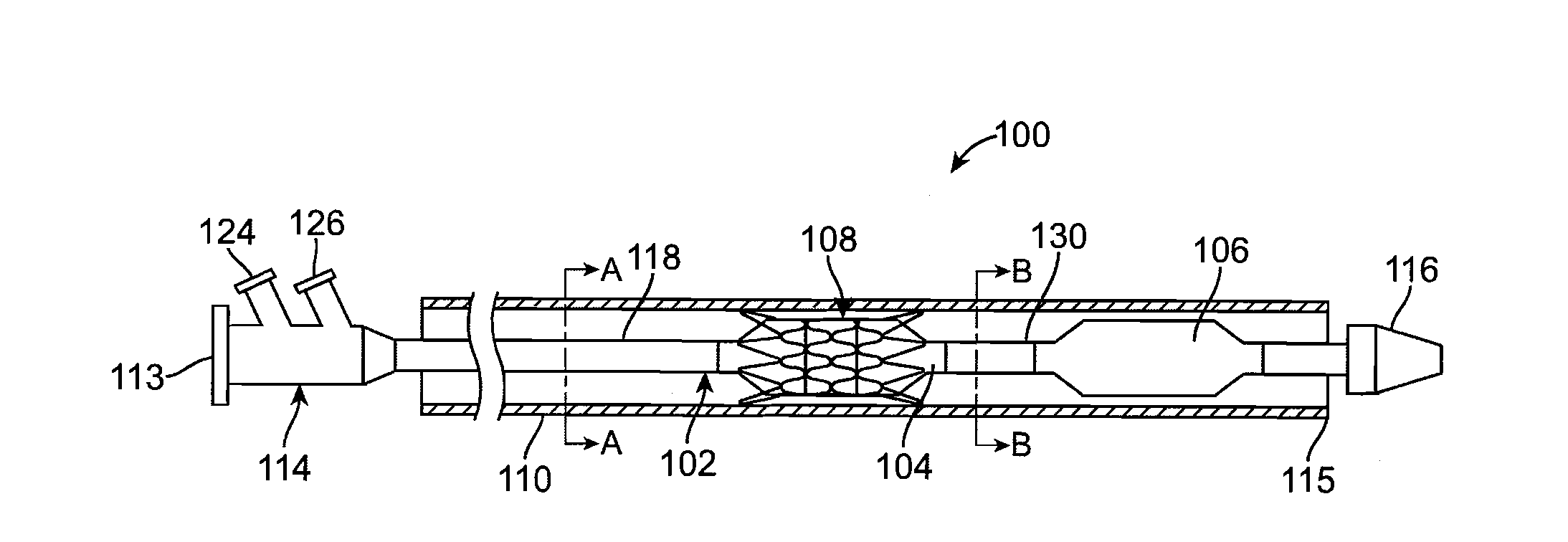
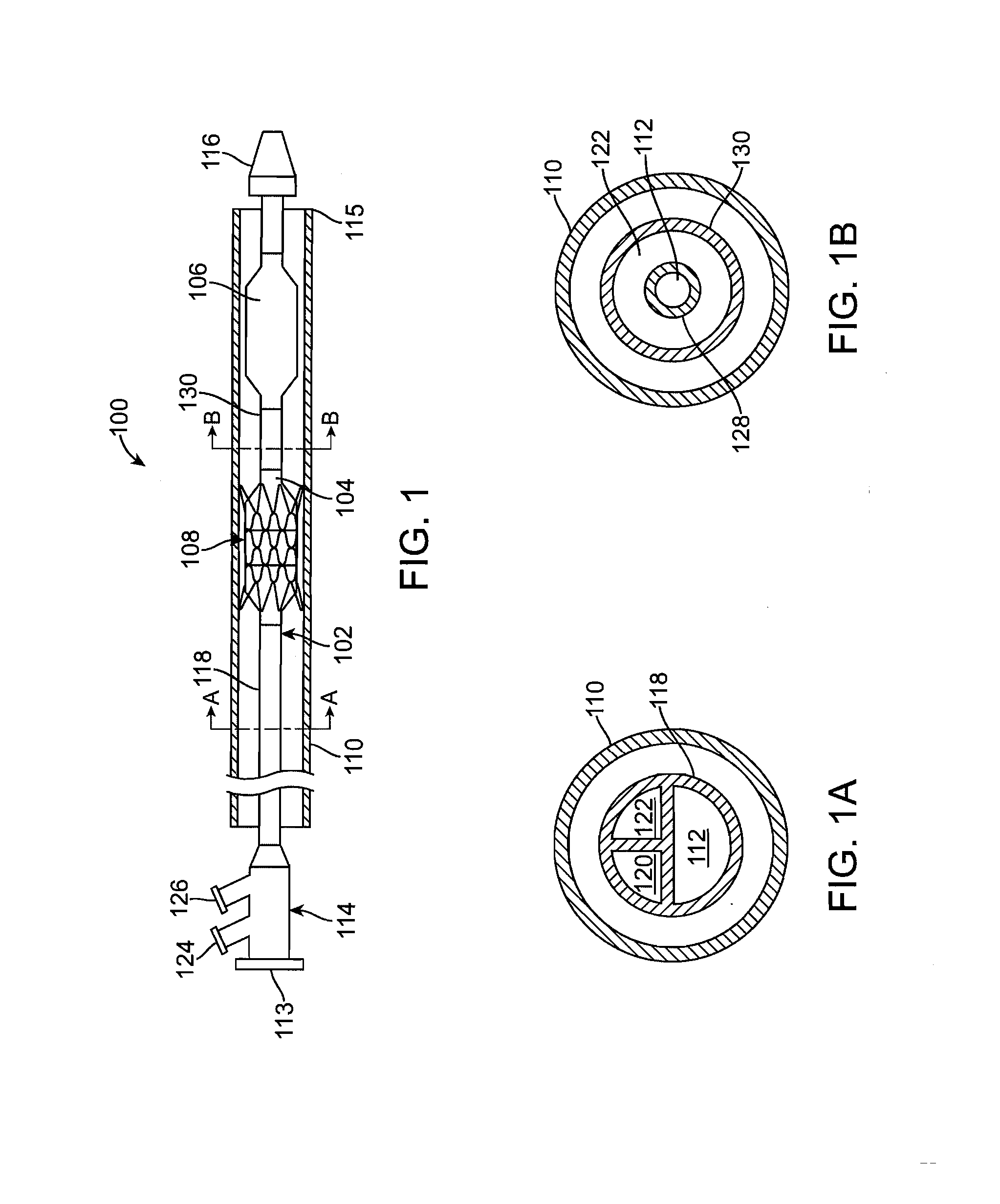
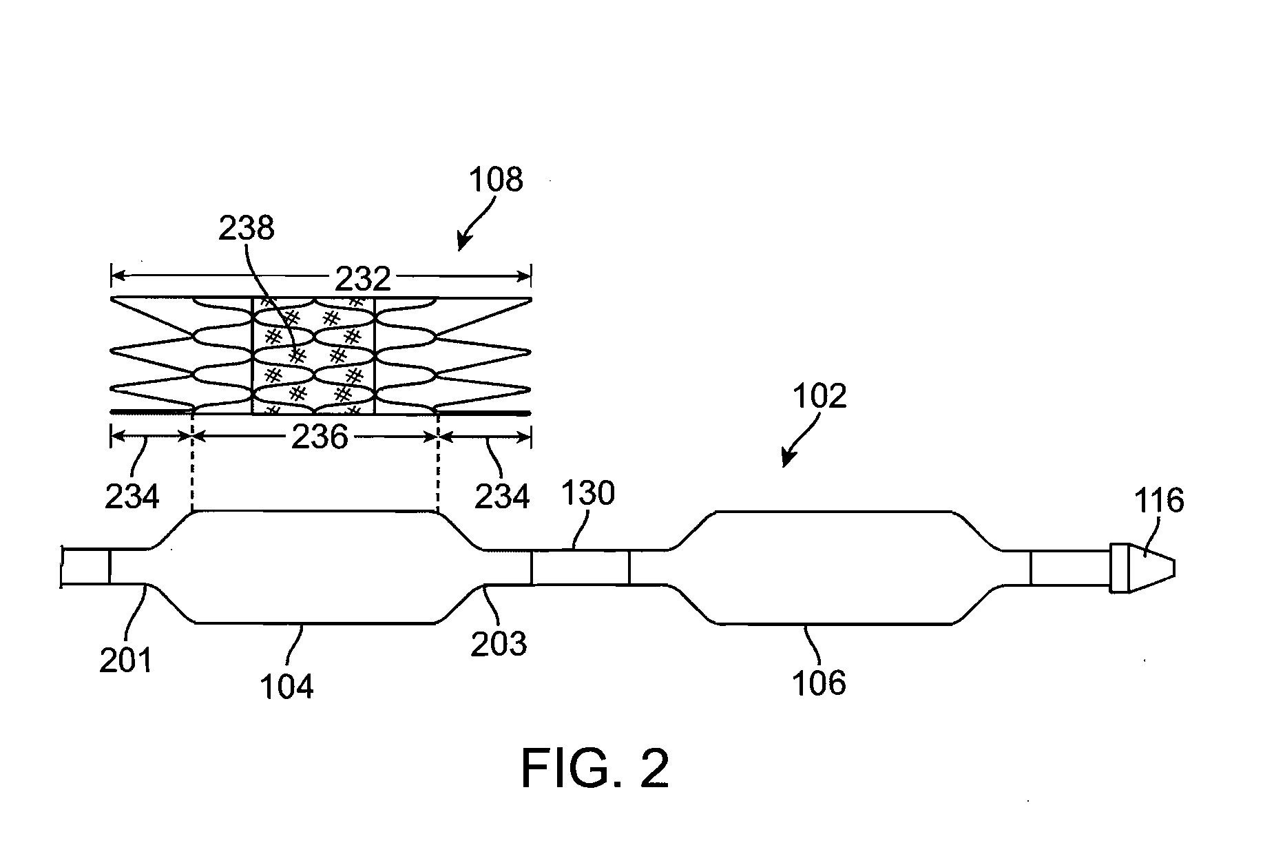
[0022]Specific embodiments of the present invention are now described with reference to the figures, wherein like reference numbers indicate identical or functionally similar elements. The terms “distal” and “proximal” are used in the following description with respect to a position or direction relative to the treating clinician. “Distal” or “distally” are a position distant from or in a direction away from the clinician. “Proximal” and “proximally” are a position near or in a direction toward the clinician. However, when discussing positions of the delivery system and / or the prosthetic valve within the aorta proximate the heart, the terms “distal” and “proximal” are used in the following description with respect to the heart. More particularly, “distal” or “distally” are a position away from the heart and “proximal” or “proximally” are a position near or closer to the heart.

[0023]The following detailed description is merely exemplary in nature and is not intended to limit the inve...


PUM


Abstract

A prosthetic valve delivery system for percutaneously delivering and deploying a prosthetic valve within an existing valve is disclosed. The delivery system includes a stented prosthetic valve having a balloon-expandable stent portion with a prosthetic valve disposed therein and at least one self-expanding stent portion. The delivery system further includes a dual balloon catheter having a first balloon on which the stented prosthetic valve is disposed during delivery and a second balloon. Upon delivery within the existing valve, the self-expanding stent portion contacts the existing valve and the first balloon expands the balloon-expandable stent portion to a first diameter such that the stented prosthetic valve is in a first stage deployment configuration. The second balloon then expands the balloon-expandable stent portion to a second diameter, greater than the first diameter, such that the stented prosthetic valve is in a second stage deployment configuration being fully deployed within the existing valve.

Description

FIELD OF THE INVENTION[0001]The invention relates generally to delivery systems for deploying a prosthetic heart valve in a non-coronary bypass procedure. More particularly, the invention relates to a catheter-based delivery system for deploying a prosthetic tissue valve having a stent framework with both balloon-expandable and self-expanding stent portions.BACKGROUND OF THE INVENTION[0002]A wide range of medical treatments are known that utilize “endoluminal prostheses.” As used herein, endoluminal prostheses are intended to mean medical devices that are adapted for temporary or permanent implantation within a body lumen, including both naturally occurring and artificially made lumens. Examples of lumens in which endoluminal prostheses may be implanted include, without limitation: arteries, such as those located within the arteries, veins gastrointestinal tract, biliary tract, urethra, trachea, hepatic and cerebral shunts, and fallopian tubes.[0003]Stent prostheses are known for im...

Claims


Application Information

Patent Timeline
Patent Type & Authority Applications(United States)
IPC IPC(8): A61F2/24A61F2/06
CPCA61F2/2418A61F2/2433A61F2/2436A61M2025/004A61M25/1011A61M29/02A61M2025/0039A61F2250/0048
Inventor DOLAN, MARK
Owner MEDTRONIC VASCULAR INC
Why Eureka
Try Eureka