

Detachable Carrying Handle For Firearm WIth Increased Range
a firearm and carrying handle technology, applied in the field of automatic firearms, can solve the problems of difficult to determine if the sights are actually aligned with the target, the specific setting of the sighting system is only accurate for a particular range of distances, and the firearm is more difficult to accurately aim
- Summary
- Abstract
- Description
- Claims
- Application Information
AI Technical Summary
Benefits of technology
Problems solved by technology
Method used
Image

Examples
Embodiment Construction
[0002]The present invention is directed to firearms and more specifically to a detachable carrying handle for use with firearms, including without limitation for use with semi-automatic and automatic firearms.
BACKGROUND OF THE INVENTION
[0003]Semi-automatic and automatic firearms are known, having been used extensively for recreational and military purposes. While such firearms have numerous objectives, several important objectives include reliability, range and accuracy.
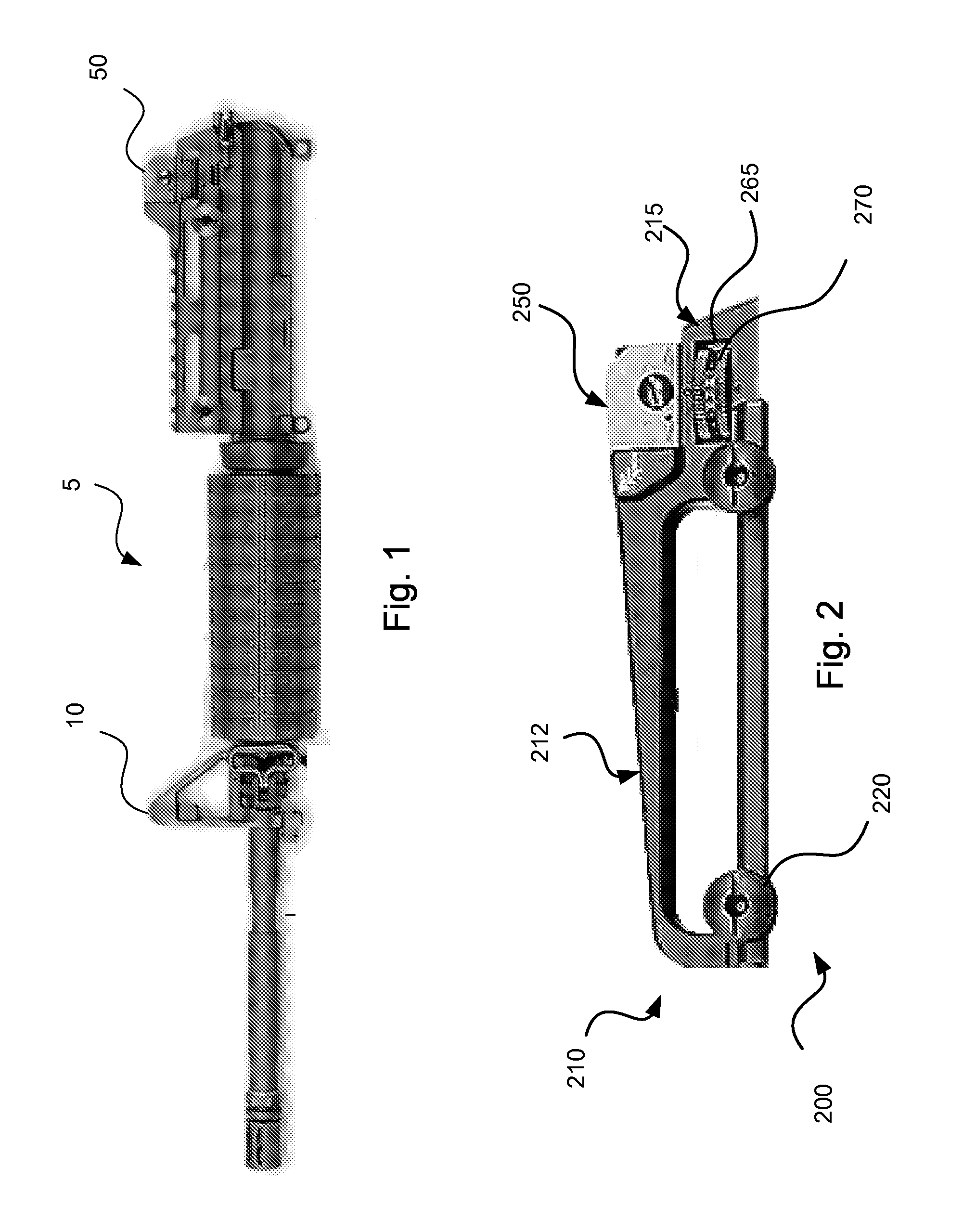
[0004]To provide increased accuracy, firearms can be equipped with a front sight system 10 and a rear sight system 50, as illustrated by the partial depiction of a firearm 5 in FIG. 1. By aligning front and rear sights, the direction of a fired bullet can be more accurately predicted. As is known, however, a particular setting of the sighting system is only accurate for a particular range of distances because a bullet drops as it travels forward due to the effects of gravity. Therefore, mechanical sighting systems ar...
PUM
 Abstract
Description
Claims
Application Information