Set-up method for array-type sound system

a sound system and array-type technology, applied in the direction of loudspeakers, gain control, stereophonic arrangments, etc., can solve the problem that there is no attempt to infer from these recordings control parameters for sound projectors

Active Publication Date: 2006-07-13
YAMAHA CORP
View PDF94 Cites 114 Cited by
  • Summary
  • Abstract
  • Description
  • Claims
  • Application Information

AI Technical Summary

Benefits of technology

[0024] The Sound Projector may be constructed so as to provide a graphical display of its perceived environment so that the user can confirm that the Sound Projector has detected the major reflection surfaces correctly.

Problems solved by technology

The problems associated with the setting up of a Sound Projector are not related to certain known methods aiming at partial or total wavefield reconstruction.
Even though these methods are inherently recording reflections from the various reflectors in a room or concert hall, no attempt is made to infer from these recordings control parameters for a Sound Projector.

Method used


Image

  • Set-up method for array-type sound system
  • Set-up method for array-type sound system
  • Set-up method for array-type sound system

Examples


Embodiment Construction

[0037] The present invention is best illustrated in connection with a digital Sound Projector as described in the co-owned applications no. WO 01 / 23104 and WO 02 / 078388. FIG. 21 of WO 01 / 23104 shows a possible arrangement, although of course the reflectors shown can be provided by the walls and / or ceiling of a room. FIG. 8 of WO 02 / 078388 shows such a configuration.

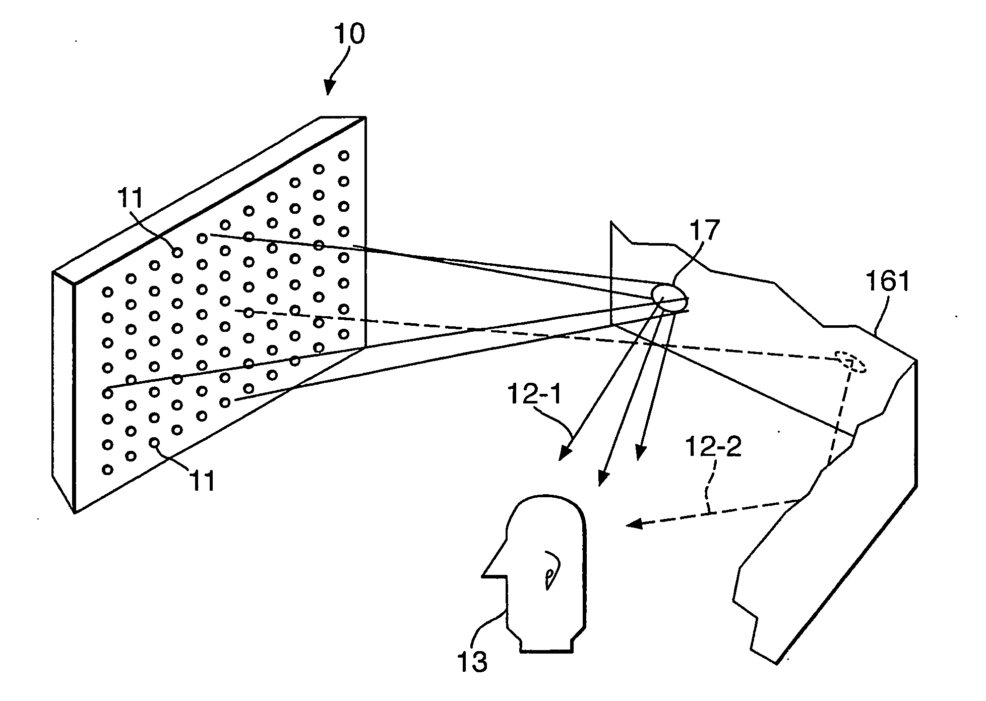
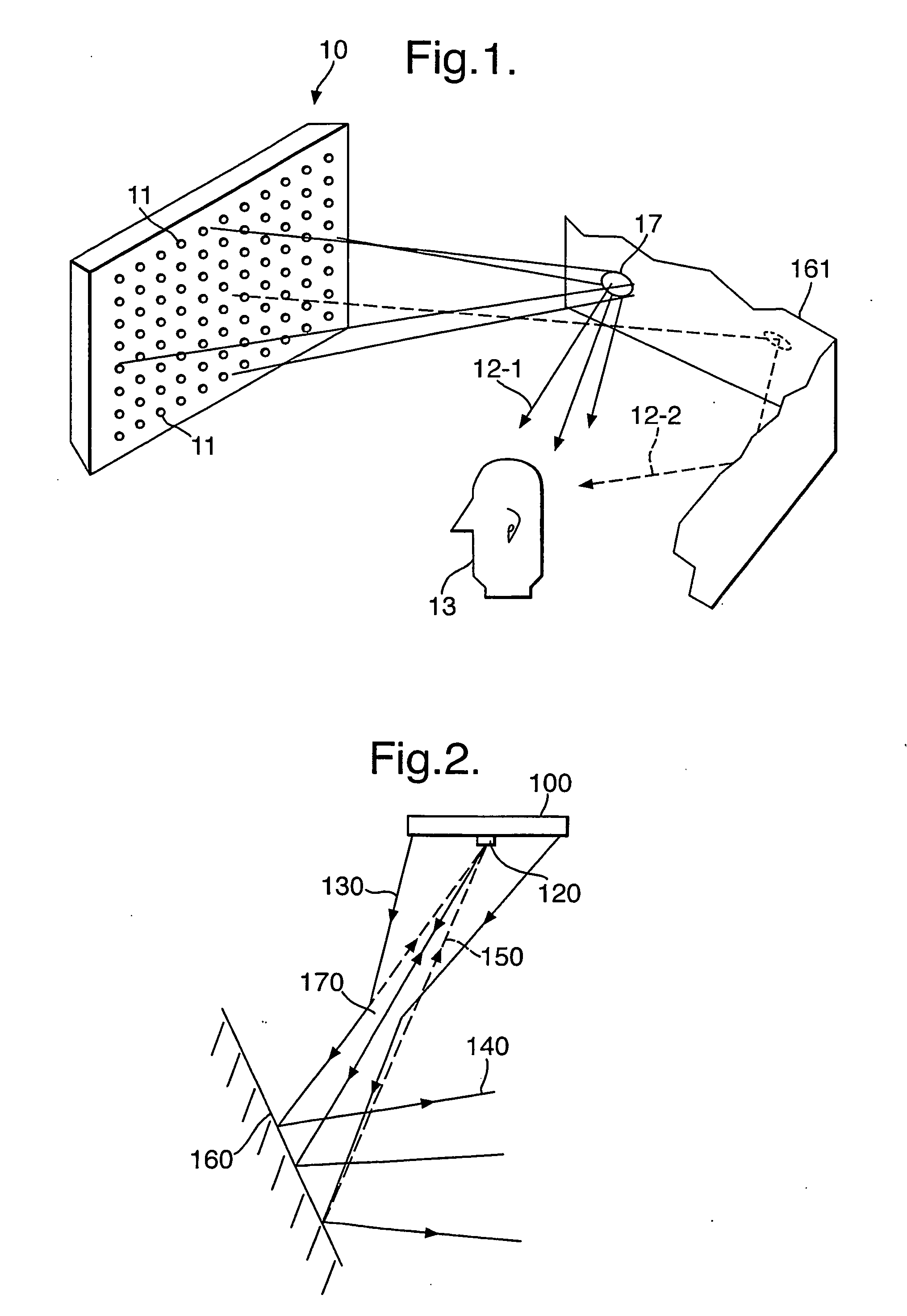
[0038] Referring to FIG. 1 of the accompanying drawings, a digital loudspeaker system or Sound Projector 10 includes an array of transducers or loudspeakers 11 that is controlled such that audio input signals are emitted as a beam or beams of sound 12-1, 12-2. The beams of sound 12-1, 12-2 can be directed into—within limits—arbitrary directions within the half-space in front of the array. By making use of carefully chosen reflection paths, a listener 13 will perceive a sound beam emitted by the array as if originating from the location of its last reflection or —more precisely— from an image of the array as reflected by ...


PUM


Abstract

There is disclosed a method for setting up a Sound Projector such that it is suitable for a variety of functions, including surround sound. The method allows a semi-automatic or automatic set-up to be accomplished whereby the Sound Projector emits test signals and these are received by one or more microphones in order to detect the position and angles of the major reflecting surfaces in the room. In a preferred embodiment, the room is scanned by a moving directional sound beam and the first reflection of said sound beam is detected at a microphone in order to determine the distance of the reflective surfaces from the Sound Projector for all or most possible angles of sound beams.

Description

FIELD OF THE INVENTION [0001] This invention concerns a device including an array of acoustic transducers capable of receiving an audio input signal and producing beams of audible sound, at a level suitable for home entertainment or professional sound reproduction applications. More specifically, the invention relates to methods and systems for configuring (i.e. setting up) such devices. BACKGROUND OF THE INVENTION [0002] The commonly-owned International Patent applications no. WO 01 / 23104 and WO 02 / 078388, the disclosure of which is hereby incorporated by reference, describe an array of transducers and their use to achieve a variety of effects. They describe methods and apparatus for taking an input signal, replicating it a number of times and modifying each of the replicas before routing them to respective output transducers such that a desired sound field is created. This sound field may comprise, inter alia, a directed, steerable beam, focussed beam or a simulated origin. The me...

Claims


Application Information

Patent Timeline
Patent Type & Authority Applications(United States)
IPC IPC(8): H04R5/00H03G3/00H04R1/40H04R3/12H04S7/00
CPCH04R1/403H04R3/12H04R2203/12H04R2205/022H04S7/301H04S7/00
Inventor HOOLEY, ANTHONYTROUGHTON, PAUL THOMASRICHARDS, DAVID CHARLES WILLIAMTURNER, DAVID CHRISTOPHER
Owner YAMAHA CORP
Why Eureka
Try Eureka