Push-button

a push-button and button technology, applied in the field of push-button, can solve the problems of inconfigurable effect push-button, inability to achieve optimum operating reliability, and inability to configure the effect of the push-button, so as to increase the redundancy of the push-button

Inactive Publication Date: 2010-09-23
W SMANN
View PDF14 Cites 38 Cited by
  • Summary
  • Abstract
  • Description
  • Claims
  • Application Information

AI Technical Summary

Benefits of technology

[0027]It is also advantageous that the haptically acting first actuation member which is associated with the push-button, the second actuation member which triggers a switching operation and the third actuation member (acoustics) which triggers a sound pulse are adjustable relative to each other. The independent adjustability and capacity for variation of the haptic electrical, acoustic switching points makes the switch usable in a versatile manner. If additional sensors are fitted, the redundancy of the push-button is increased.
[0028]It is further advantageous for the first actuation member to be formed by the contour module and the torsion spring and for the actuation member which triggers a haptic control signal to comprise a guide contour provided in the housing and the actuation element which co-operates therewith, which is in the form of a torsion spring and which can be guided along the guide contour of the actuation member by means of the push-button actuation element.

Problems solved by technology

This solution does not have a defined, selectively influencable haptic or acoustic response.
Non-optimum operating reliability produces an impression of quality which is inferior.
Furthermore, the Hall effect push-button is not configured so as to be redundant and is consequently not protected sufficiently from failure.
If a spring breakage occurs in this switch, the push-button is not switched off and the machine which can be actuated by means of the switch is placed in an uncontrollable state.
Push-buttons having conventional switching contacts always have the problem that the response is coupled to the switching operation.
The haptic action of the above-mentioned push-button can be changed only if the switching element is reconfigured, which again results in a high level of development complexity and high costs for tool construction.

Method used


Image

  • Push-button
  • Push-button
  • Push-button

Examples


Embodiment Construction

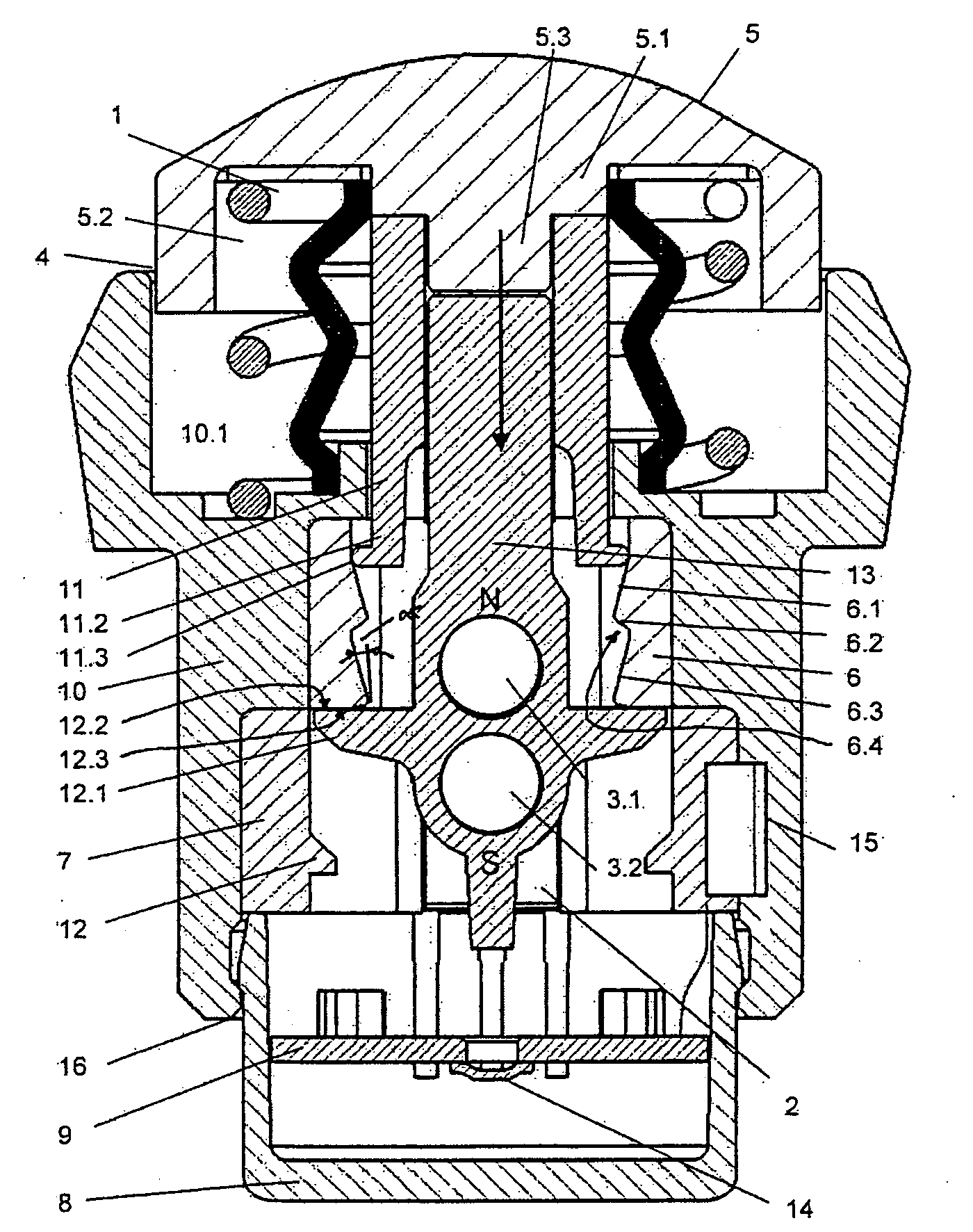
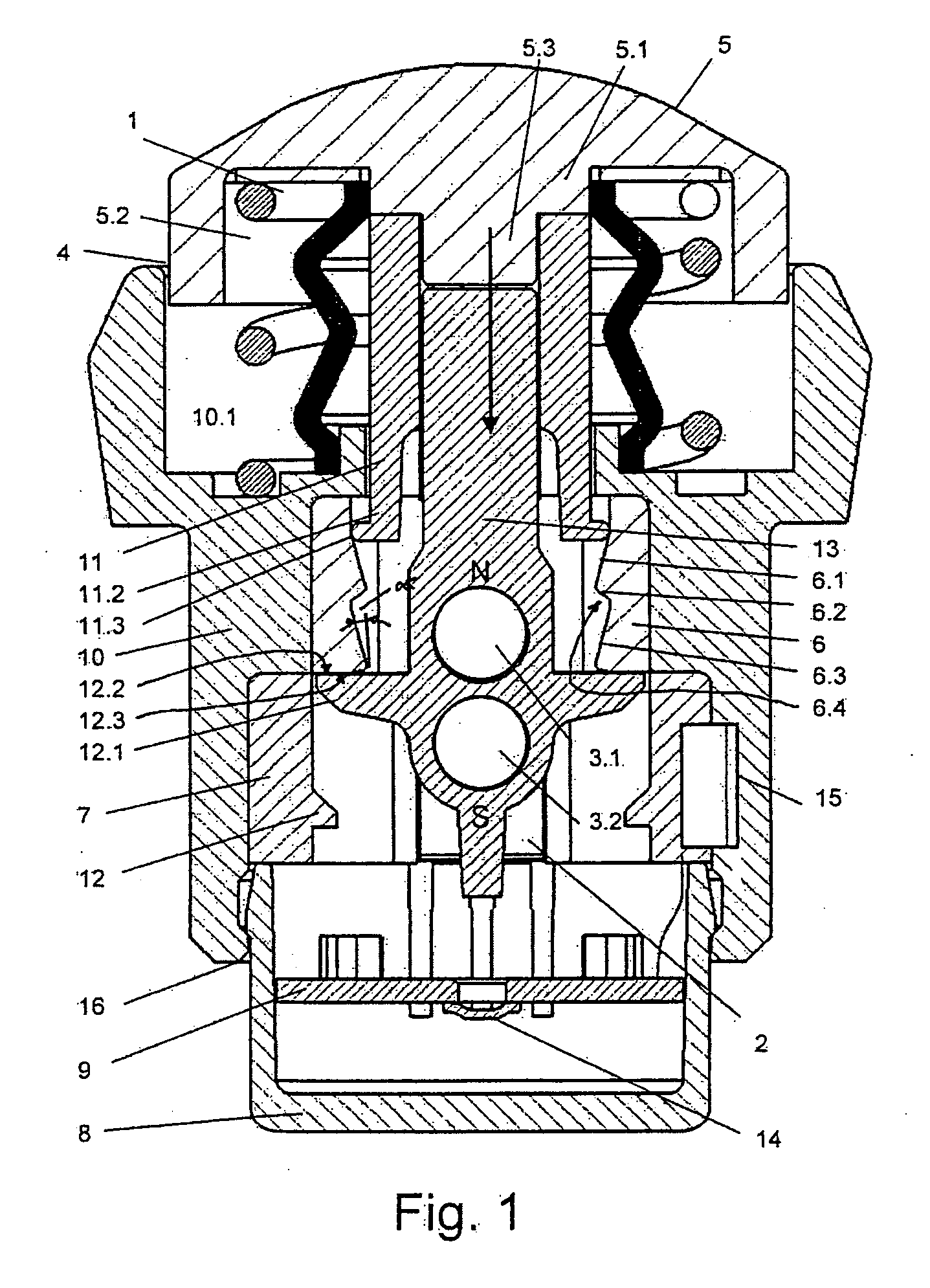
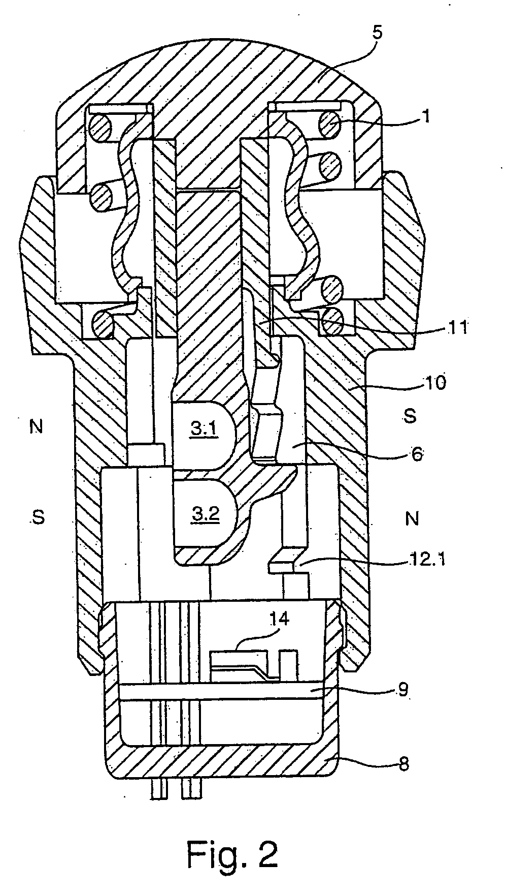
[0035]The drawings illustrate a push-button 5 having a tappet 13, which is supported so as to be movable in a housing 10 counter to the action of a restoring spring 1. The housing 10 is in the form of a cylindrical sleeve and has, at its upper end, a recess 10.1 for receiving the lower end of the restoring spring 1 which is received, with its other end, in a recess 5.2 which is provided in a push-button cap 5.1 and thereby moves the push-button cap 5.1 or the push-button actuation element into the inactive position or initial position thereof. A torsion spring 11 is constructed at least partially as a sleeve which, on the one hand, is connected to a cylindrical journal 5.3 which is securely connected to the push-button actuation element 5.1 and, on the other hand, has resilient torsion spring elements 11.2. The torsion spring 11 and the tappet 13 may also be one part.

[0036]An air gap 4 is provided between the outer periphery of the push-button actuation element 5.1 and the inner per...


PUM


Abstract

The invention relates to a push-button (5) having a housing (10), with which there are associated at least a first actuation member (6) which triggers a haptic control signal and one or more permanent magnet(s) (3) which can be guided past at least a second actuation member (2) which triggers a switching operation.
There is associated with the first actuation member (6), which triggers a haptic response, a control element having a first progressive or degressive control face portion (6.1) and at least a second adjoining control face portion (6.2) which behaves in an inverse manner and along which the actuation member is guided.

Description

[0001]The present invention relates to a push-button having a housing, with which there are associated at least a first actuation member which triggers a haptic control signal and one or more permanent magnet(s) which can be guided past at least a second actuation member which triggers a switching operation.[0002]There is already known (U.S. Pat. No. 6,867,680B1) a push-button which has a tappet which is supported in a housing so as to be movable counter to the effect of a restoring spring and with which there are associated at least one haptically acting control signal, a haptic triggering actuation element in the form of a ball and two permanent magnets which trigger at least one switching pulse at a second actuating member or a Hall sensor, which triggers a switching operation when the tappet with its magnets is moved past the Hall sensor. This solution does not have a defined, selectively influencable haptic or acoustic response.[0003]The haptic action of the previously known so...

Claims


Application Information

Patent Timeline
Patent Type & Authority Applications(United States)
IPC IPC(8): H01H13/14
CPCH01H3/022H01H13/52H01H2239/024H01H2239/006H01H2239/022H01H2215/00
Inventor WILD, JORGREISINGER, JORGHOGER, OLIVERRADES, NIKOLAUS
Owner W SMANN
Why Eureka
Try Eureka