Lower vehicle-body structure of vehicle

a vehicle body and lower technology, applied in the direction of roofs, transportation and packaging, vehicle arrangements, etc., can solve the problem of side sills breaking

Active Publication Date: 2010-09-23
MAZDA MOTOR CORP
View PDF10 Cites 51 Cited by
  • Summary
  • Abstract
  • Description
  • Claims
  • Application Information

AI Technical Summary

Benefits of technology

[0005]An object of the present invention is to provide a lower vehicle-body structure of a vehicle which can properly restrain the side sill and the center pillar from coming toward the vehicle inside at the vehicle side crash.

Problems solved by technology

Thus, there occurs a case in which the connection portion of the side sill to the center pillar moves toward the vehicle inside, so that the side sill may break.

Method used


Image

  • Lower vehicle-body structure of vehicle
  • Lower vehicle-body structure of vehicle
  • Lower vehicle-body structure of vehicle

Examples


embodiment 1

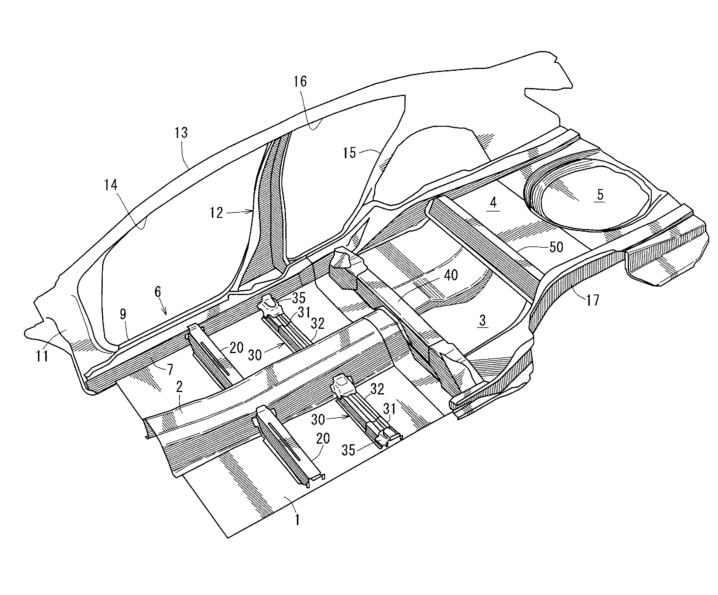
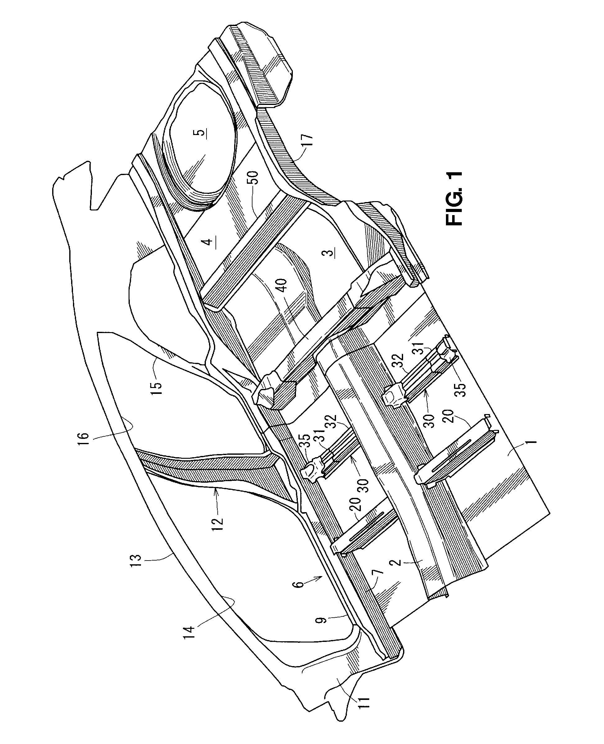
[0054]In FIG. 1, a floor panel (front floor panel) 1 which forms a bottom face of a vehicle compartment is provided, and a tunnel portion 2 (a so-called floor tunnel) which projects upward and extends in a vehicle longitudinal direction is integrally formed at the center of the floor panel 1 in a vehicle width direction. This tunnel portion 2 constitutes the vehicle-body rigidity mainly.

[0055]A rear seat pan 3 is provided at a rear portion of the floor panel 1. A rear floor (panel) 4 which forms a bottom face of a baggage compartment is provided continuously in back of the rear seat pan 3. A concave spare pan 5 is integrally formed at the center of a rear portion of the rear floor 4.

[0056]Further, a pair of side sills 6, as vehicle-body rigidity member, which extends in the vehicle longitudinal direction, is provided at both sides of the floor panel 1 (only the side sill on the right is illustrated in the figure). The side sill 6 is a strength member which is made of a side-sill inn...

embodiment 2

[0116]In place of the disposition structure of the reinforcing member 51 and the outer gusset 54 which are shown in FIG. 12, another disposition structure of those members 51, 54 which is shown in FIG. 18 may be applied. That is, in the structure shown in FIG. 18 (herein, FIG. 18 is a perspective view showing the inside structure of the side sill 6, in which illustrations of the side-sill inner 7, the center-pillar inner 41 and others are omitted, like FIG. 12), the front and rear outer gussets 54, 54 are provided inside the side-sill reinforcement 8 at specified positions which correspond to the front and rear cross members 20, 40 in front and back of the center pillar 12 so as to form the node in the cross section of the side-sill reinforcement 8, and the reinforcing member 51 is arranged over a range between the front and rear gussets 54, 54. That is, the outer gussets 54, 54 are located at the positions of the cross members 20, 40, and the reinforcing member 51 is located betwee...


PUM


Abstract

A reinforcing member is provided at a lower-outside corner of a side-sill reinforcement so as to extend in the vehicle longitudinal direction including a connection portion of the side sill to a center pillar for straining deformation of the corner. A deformation promoting portion which is provided at an upper portion of the side-sill reinforcement at a specified position which corresponds to the connection portion for prompting deformation of the upper portion of the side-sill reinforcement. Accordingly, a lower vehicle-body structure of a vehicle which can properly restrain the side sill and the center pillar from coming toward the vehicle inside at the vehicle side crash can be provided.

Description

BACKGROUND OF THE INVENTION[0001]The present invention relates to a lower vehicle-body structure of a vehicle which comprises a side sill which extends in a vehicle longitudinal direction, a center pillar which extends in a vertical direction and is connected to the side sill at a lower end thereof, and a side-sill reinforcement which is provided inside the side sill and has a U-shaped cross section opening toward a vehicle inside.[0002]In the conventional lower vehicle-body structure of a vehicle, the lower end of the center pillar extending in the vertical direction is connected to the side sill extending in the vehicle longitudinal direction. According to this conventional lower vehicle-body structure, in case a load of a vehicle side crash is inputted to the center pillar at the vehicle side crash, the crash load is transmitted to a connection portion of the side sill to the center pillar toward the vehicle inside. Thus, there occurs a case in which the connection portion of the...

Claims


Application Information

Patent Timeline
Patent Type & Authority Applications(United States)
IPC IPC(8): B62D25/20
CPCB62D21/157B60N2/005B62D25/2036B62D25/025
Inventor ISHIGAME, KATSUYOSHISUGIMURA, YUICHIMOTOKI, MASAKIFUJII, YUKARIYUKIMORI, AKIHIRONISHIMURA, YOSHIKAZUKIRITA, KOHEIEJIMA, KATSUMIKAWASAKI, KEIZO
Owner MAZDA MOTOR CORP
Why Eureka
Try Eureka