Assembled battery system and assembled battery protection device
- Summary
- Abstract
- Description
- Claims
- Application Information
AI Technical Summary
Problems solved by technology
Method used
Image
Examples
first embodiment
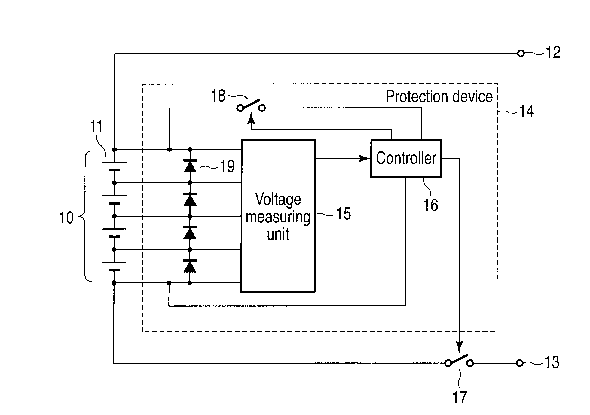
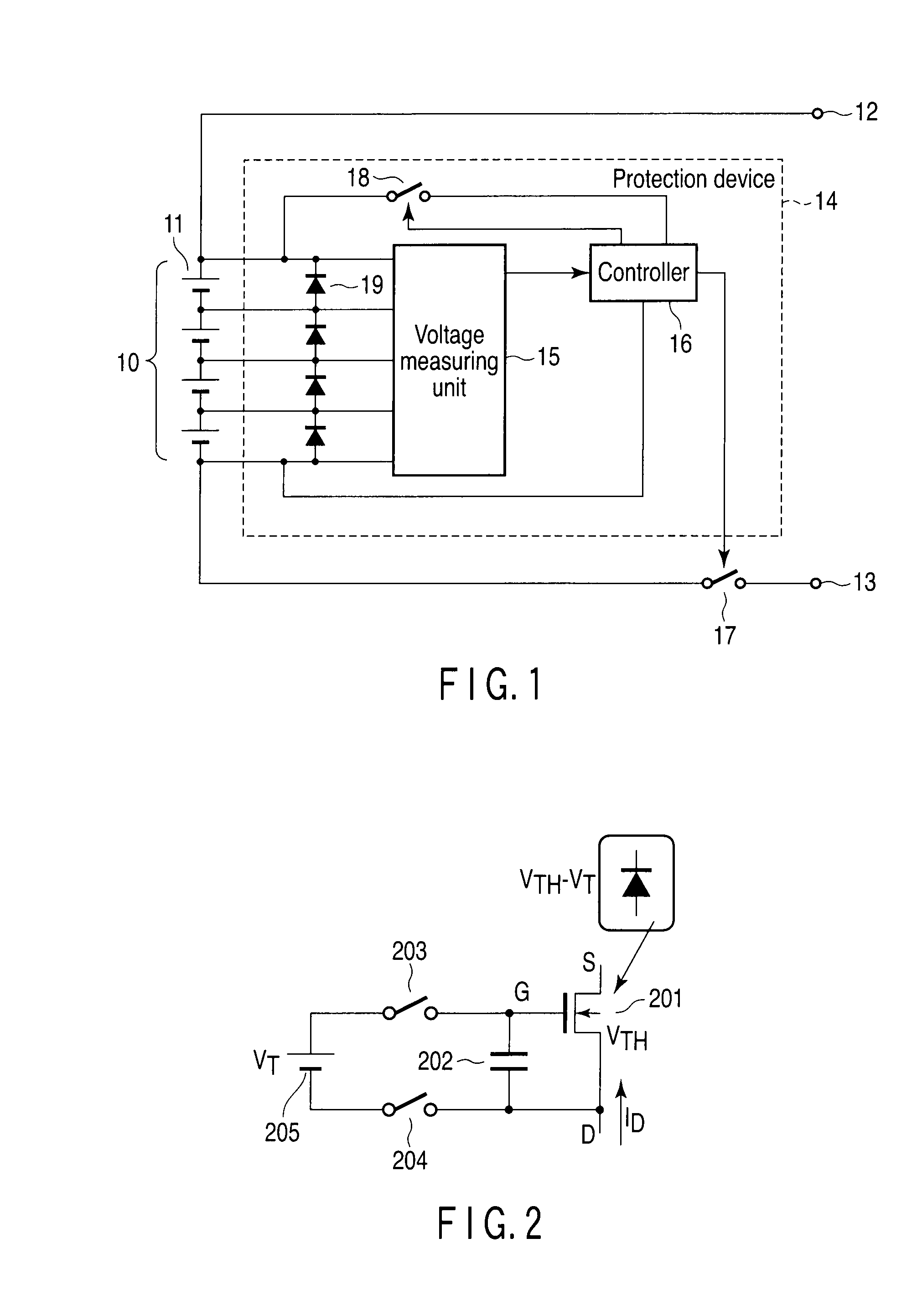
[0024]FIG. 1 shows an assembled battery system according to a first embodiment. The assembled battery system mainly comprises an assembled battery 10 and a protection device 14. The assembled battery 10 comprises a plurality of electric cell blocks 11 connected in series. Each electric cell block 11 uses at least one nonaqueous electrolyte secondary battery as an electric cell. When each electric cell block 11 includes a plurality of nonaqueous electrolyte secondary batteries, these batteries are connected in parallel. Each nonaqueous electrolyte secondary battery includes a negative electrode power collector formed of aluminum or an aluminum alloy.
[0025]The positive and negative terminals of the assembled battery 10 are connected to external terminals 12 and 13, respectively. The external terminals 12 and 13 are connected to a charging power supply for the assembled battery 10 during the charge of the assembled battery 10, and to a load during the discharge of the assembled battery...
second embodiment
[0045]FIG. 5 shows an assembled battery system according to a second embodiment. The assembled battery system of the second embodiment differs from that of the first embodiment in that the former additionally incorporates SOC balancers 20 connected in parallel to the respective electric cell blocks 11, and a storage unit 23 connected to the controller 16. Firstly, the SOC balancer 20 will be described.
[0046]As described above, in the assembled battery 10 including a plurality of electric cell blocks 11 connected in series, variations in characteristics therebetween, in particular, SOC variations, which are most liable to cause malfunctions, are problematic. In the assembled battery 10, when the electric cell blocks 11 are connected in series with the SOC variations left therein, if the assembled battery 10 is charged, the electric cell blocks 11 may vary in voltage, and only part of the blocks 11 be overcharged.
[0047]The SOC variations may be caused by a factor that will occur durin...
third embodiment
[0056]In the above-described second embodiment, the SOC balancers 20 each formed of the semiconductor switch 21 and the resistor 22 are controlled in relation to the bypass histories stored in the storage unit 23 for the respective electric cell blocks 11. On the other hand, in a third embodiment described below, the SOC balancers are realized by other manners.
[0057]FIG. 7 shows an example of a bypass circuit 19 according to the third embodiment, which also has a function equivalent to, for example, three SOC balancers connected in series and corresponding to three electric cell blocks connected in series. In the third embodiment, the bias voltage VT applied to the MOSFET 201 of the bypass circuit 19 of each electric cell block 11 is changed to, for example, VT1, VT2 and VT3 in accordance with SOC variations, thereby changing the apparent threshold voltage VTH of the MOSFET 201. This enables the bypass circuit 19 of each electric cell block 11 to discharge a necessary discharge curr...
PUM
 Abstract
Description
Claims
Application Information
 - R&D
- Intellectual Property
- Life Sciences
- Materials
- Tech Scout
- Unparalleled Data Quality
- Higher Quality Content
- 60% Fewer Hallucinations
Browse by: Latest US Patents, China's latest patents, Technical Efficacy Thesaurus, Application Domain, Technology Topic, Popular Technical Reports.
© 2025 PatSnap. All rights reserved.Legal|Privacy policy|Modern Slavery Act Transparency Statement|Sitemap|About US| Contact US: help@patsnap.com


