Compensation of Optical Transmission Impairments Using Digital Backward Propagation

a technology of backward propagation and compensating for optical transmission impairments, applied in the direction of fiber transmission, distortion/dispersion elimination, wavelength-division multiplex systems, etc., can solve problems such as limiting the carrying capacity of these systems

Active Publication Date: 2010-09-23
UNIV OF CENT FLORIDA RES FOUND INC
View PDF3 Cites 29 Cited by
  • Summary
  • Abstract
  • Description
  • Claims
  • Application Information

AI Technical Summary

Problems solved by technology

Channel impairments in transmission systems result in signal de

Method used


Image

  • Compensation of Optical Transmission Impairments Using Digital Backward Propagation
  • Compensation of Optical Transmission Impairments Using Digital Backward Propagation
  • Compensation of Optical Transmission Impairments Using Digital Backward Propagation

Examples


Embodiment Construction

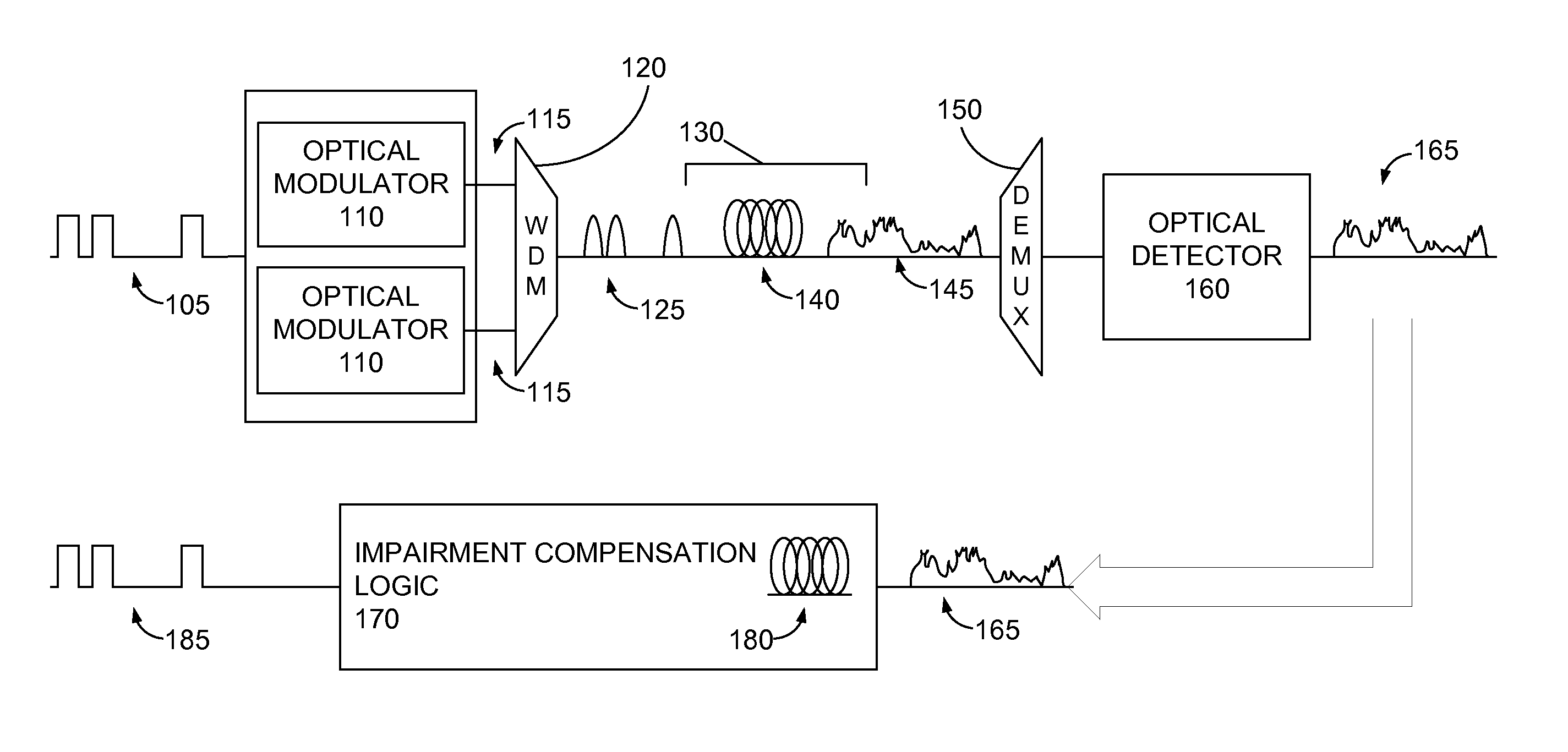
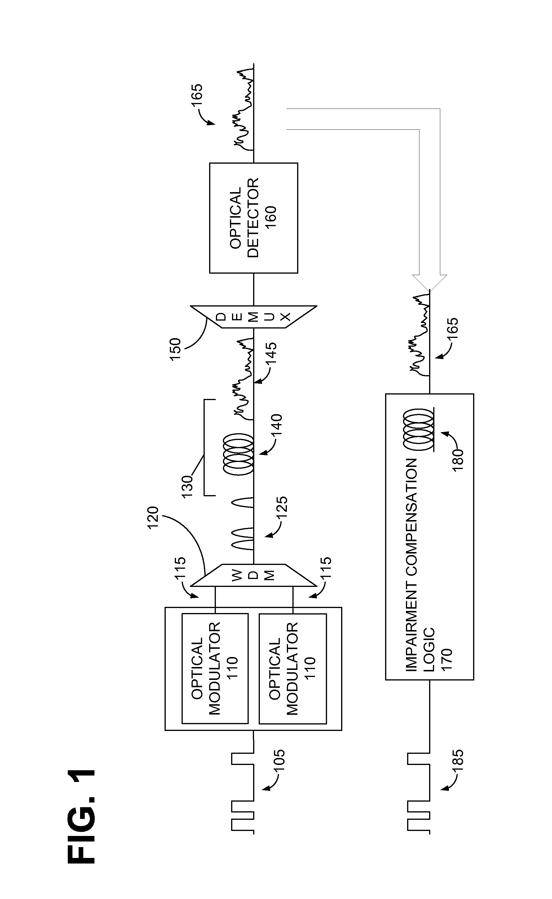
[0012]The inventive techniques described herein compensate for optical distortion, using backward propagation in the electrical domain. Specifically, digital backward propagation in the digital domain is used to convert the received optical signal into an estimate of the transmitted signal. This digital backward propagation process involves solving one or more equations which model a virtual optical transmission channel corresponding to the physical optical transmission channel. The model uses channel parameter values that are opposite to (“backward” from) the physical channel parameters. Applying the model to the received optical signal thus compensates for impairments produced by the physical channel.

[0013]FIG. 1 is a system model diagram of an optical communication system including an embodiment of impairment compensation logic. Transmitted data is carried by an electrical signal 105, which is provided to a set of optical modulators 110. Each optical modulator 110, operating at a...


PUM


Abstract

Systems and method of compensating for transmission impairment are disclosed. One such method comprises receiving a wavelength-division multiplexed optical signal. The received optical signal has been distorted in the physical domain by an optical transmission channel. The method further comprises propagating the distorted optical signal backward in the electronic domain in a corresponding virtual optical transmission channel. The backward propagation fully compensates for fiber dispersion, self-phase modulation, and cross-phase modulation (XPM) and partially compensates for four-wave mixing (FWM).

Description

CROSS-REFERENCE TO RELATED APPLICATIONS[0001]This application claims priority to copending U.S. Provisional Application having Ser. No. 61 / 161,867, filed Mar. 20, 2009, which is hereby incorporated by reference herein in its entirety.FIELD OF THE DISCLOSURE[0002]The present disclosure relates to compensating for optical transmission impairments in the electronic or software domain.BACKGROUND[0003]Channel impairments in transmission systems result in signal degradation and thus limit the carrying capacity of these systems. In optical transmission systems, some of these impairments are linear (e.g., fiber chromatic dispersion or CD) and some are non-linear (e.g., cross-phase modulation and four-wave mixing caused by the Kerr effect). To minimize the effect of impairments, transmission systems may include various types of compensation systems or devices. A signal can be modified before, or as part of, transmission to account for the effect of impairment (a technique known as pre-compen...

Claims


Application Information

Patent Timeline
IPC IPC(8): H04J14/02
CPCH04J14/002H04B10/2507
Inventor LI, GUIFANGMATEO, EDUARDOYAMAN, FATIH
Owner UNIV OF CENT FLORIDA RES FOUND INC
Why Eureka
Try Eureka