
Lithium-ion battery

a technology of lithium-ion batteries and ion batteries, which is applied in the field of lithium-ion batteries, can solve the problems of battery cases that exhibit battery that exhibits a dramatic loss of deliverable capacity, and reduces the protection against future over-discharge conditions

Active Publication Date: 2010-09-23
MEDTRONIC INC
View PDF99 Cites 9 Cited by
  • Summary
  • Abstract
  • Description
  • Claims
  • Application Information

AI Technical Summary

Benefits of technology

[0017]Another exemplary embodiment relates to a battery that includes a positive electrode and a negative electrode, the positive electrode comprising a first active material selected from the group consisting of LiCoO2 and LiMn2O4 and the negative electrode comprising a second act

Problems solved by technology

One difficulty with conventional lithium-ion batteries is that when such a battery is discharged to a point near zero volts, it may exhibit a loss of deliverable capacity and corrosion of the negative electrode current collector (copper) and possibly of the battery case, depending on the material used and the polarity of the case.
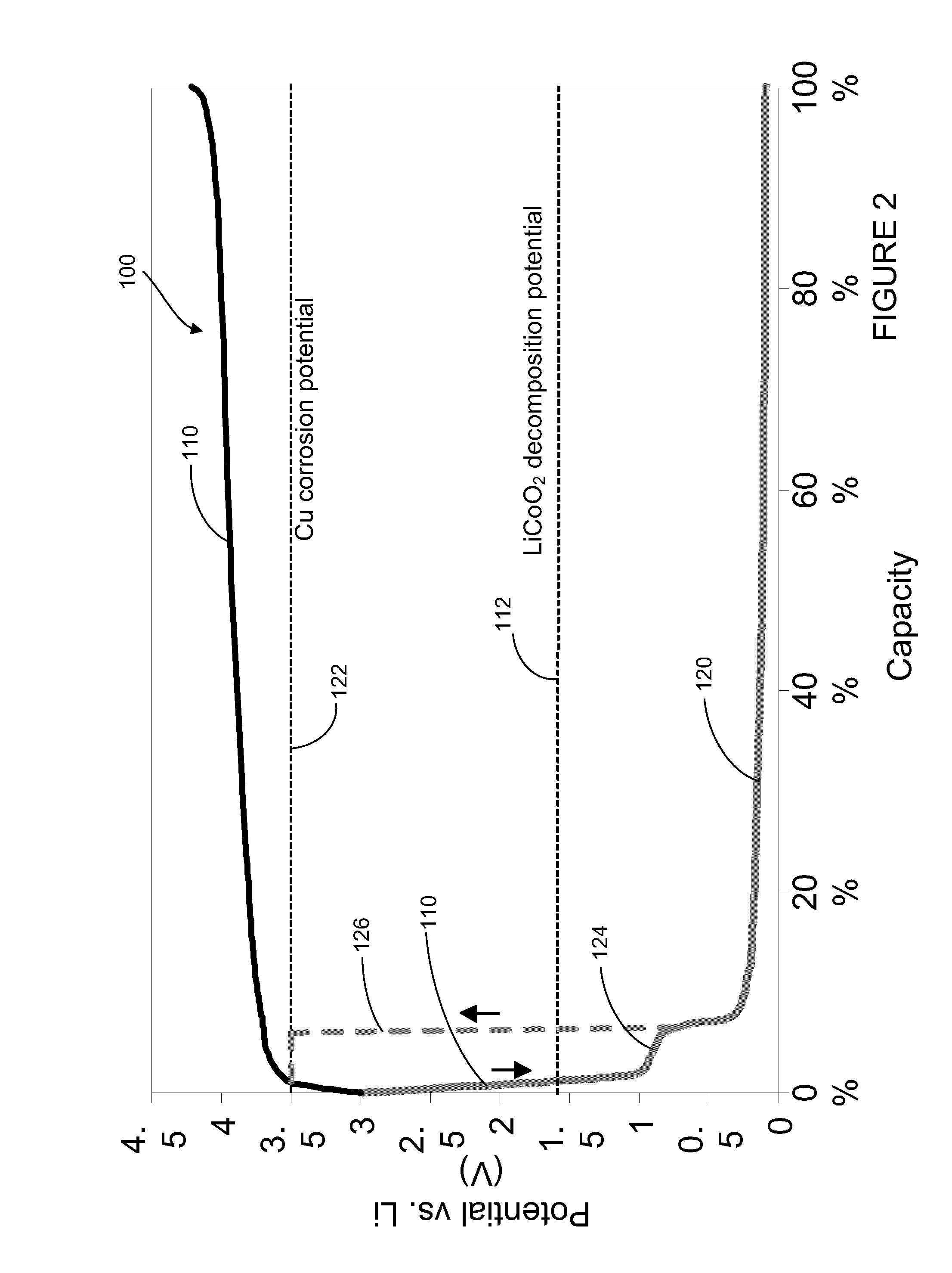
Because of the degradation of the copper current collector which occurs at the copper corrosion potential, the copper material used for the negative current collector corrodes before the cell reaches a zero voltage condition, resulting in a battery that exhibits a dramatic loss of deliverable capacity.
In such cases, the theoretical potential of the positive electrode versus a lithium reference electrode would decrease to the decomposition potential of the positive active material (shown as line 112 in FIG. 2), at which point the positive active material would decompose, resulting in potentially decreased protection against future over-discharge conditions.

Method used


Image

  • Lithium-ion battery
  • Lithium-ion battery
  • Lithium-ion battery

Examples


Embodiment Construction

[0025]With reference to FIG. 3, a schematic cross-sectional view of a portion of a lithium-ion battery 200 is shown according to an exemplary embodiment. According to an exemplary embodiment, the battery 200 has a rating of between approximately 10 and 1000 milliampere hours (mAh). According to another exemplary embodiment, the battery has a rating of between approximately 100 and 400 mAh. According to another exemplary embodiment, the battery is an approximately 300 mAh battery. According to another exemplary embodiment, the battery is an approximately 75 mAh battery.

[0026]The battery 200 includes at least one positive electrode 210 and at least one negative electrode 220. The electrodes may be provided as flat or planar components of the battery 200, may be wound in a spiral or other configuration, or may be provided in a folded configuration. For example, the electrodes may be wrapped around a relatively rectangular mandrel such that they form an oval wound coil for insertion int...


PUM


Abstract

A lithium-ion battery includes a positive electrode comprising a current collector and a first active material and a negative electrode comprising a current collector, a second active material, and a third active material. The second active material comprises a lithium titanate material and the third active material is selected from the group consisting of LixVO2 where x is between 0.05 and 0.4, LiMxMn(2−x)O4 where M is a metal and x is less than or equal to 1, V6O13, V2O5, V3O8, MoO3, TiS2, WO2, MoO2, RuO2, and combinations thereof. The third active material exhibits charging and discharging capacity below a corrosion potential of the current collector of the negative electrode and above a decomposition potential of the first active material.

Description

CROSS-REFERENCE TO RELATED APPLICATIONS[0001]The present application is a Divisional of U.S. patent application Ser. No. 12 / 429,061 filed Apr. 23, 2009, which is a Divisional of U.S. patent application Ser. No. 10 / 978,617 filed Oct. 29, 2004. The entire disclosures of U.S. patent application Ser. No. 12 / 429,061 and U.S. patent application Ser. No. 10 / 978,617 are incorporated herein by reference.BACKGROUND[0002]The present invention relates generally to the field of lithium batteries. Specifically, the present invention relates to lithium-ion batteries that are relatively tolerant to over-discharge conditions.[0003]Lithium-ion batteries include a positive current collector (e.g., aluminum such as an aluminum foil) having an active material provided thereon (e.g., LiCoO2) and a negative current collector (e.g., copper such as a copper foil) having an active material (e.g., a carbonaceous material such as graphite) provided thereon. Together the positive current collector and the activ...

Claims


Application Information

Patent Timeline
IPC IPC(8): H01M4/02H01M4/50H01M4/58H01M4/131H01M4/133H01M4/136H01M4/48H01M4/485H01M4/505H01M4/52H01M4/525H01M10/0525H01M10/36
CPCA61N1/08Y02E60/122A61N1/378H01M4/131H01M4/133H01M4/136H01M4/362H01M4/382H01M4/485H01M4/505H01M4/525H01M4/5815H01M4/5825H01M4/661H01M10/0525H01M10/4235A61N1/3605Y02E60/10
Inventor HOWARD, WILLIAM G.SCHMIDT, CRAIG L.SCOTT, ERIK R.
Owner MEDTRONIC INC
Learn More