Supercharge Your Innovation With Domain-Expert AI Agents!

Linking element of a vertebral osteosynthesis device and vertebral osteosynthesis device compromising it

a technology of vertebral osteosynthesis and linking element, which is applied in the field of prosthesis, can solve problems such as making the risky implantation of bone screws

Inactive Publication Date: 2010-09-23
WARSAW ORTHOPEDIC INC
View PDF28 Cites 10 Cited by
  • Summary
  • Abstract
  • Description
  • Claims
  • Application Information

AI Technical Summary

Benefits of technology

[0006]To this effect, the present invention relates to a linking element for linking a longitudinal element of a vertebral osteosynthesis device with a vertebra, that is characterized in that it comprises a left linking part and a right linking part, each intended to extend on the left side and

Problems solved by technology

The posterior approach may be more indicated in the case where osteoporosis weakens the spongy part of the vertebrae, and makes the implantation of bone screws risky in regions where the spongy bone is particularly thick, as is the case in the anterior part of the vertebrae.

Method used


Image

  • Linking element of a vertebral osteosynthesis device and vertebral osteosynthesis device compromising it
  • Linking element of a vertebral osteosynthesis device and vertebral osteosynthesis device compromising it
  • Linking element of a vertebral osteosynthesis device and vertebral osteosynthesis device compromising it

Examples


Embodiment Construction

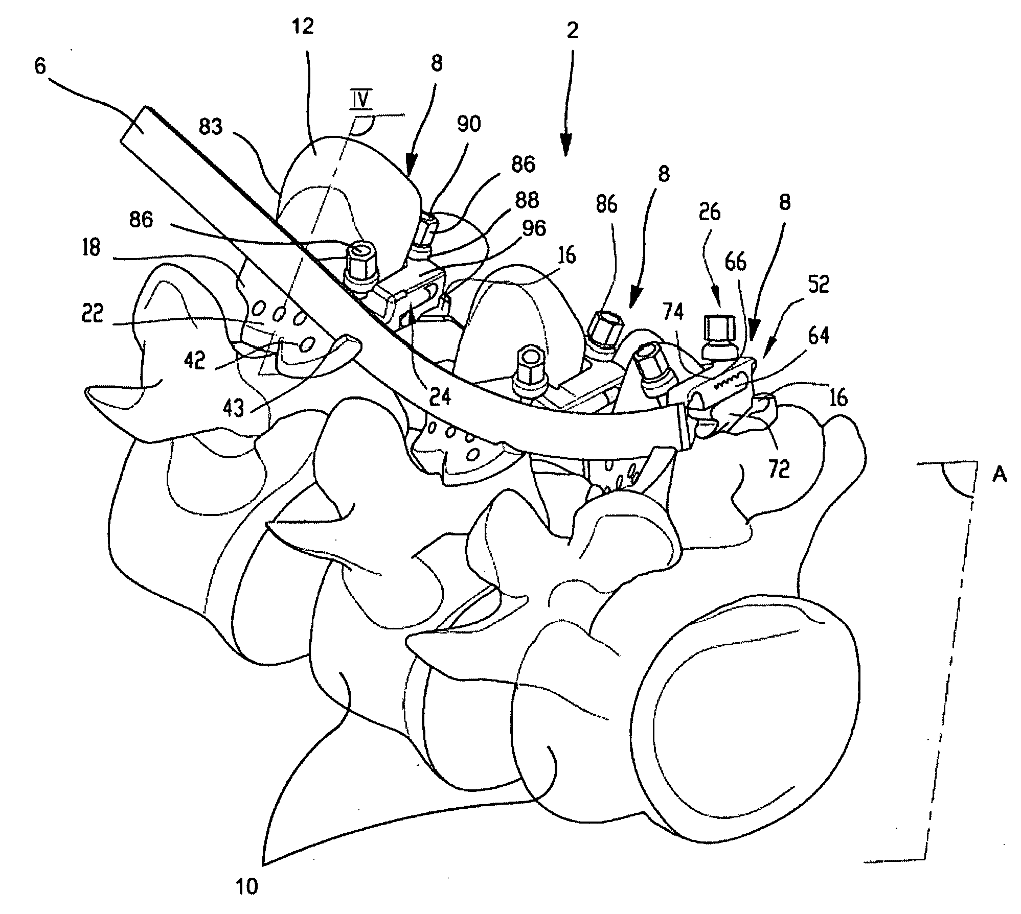
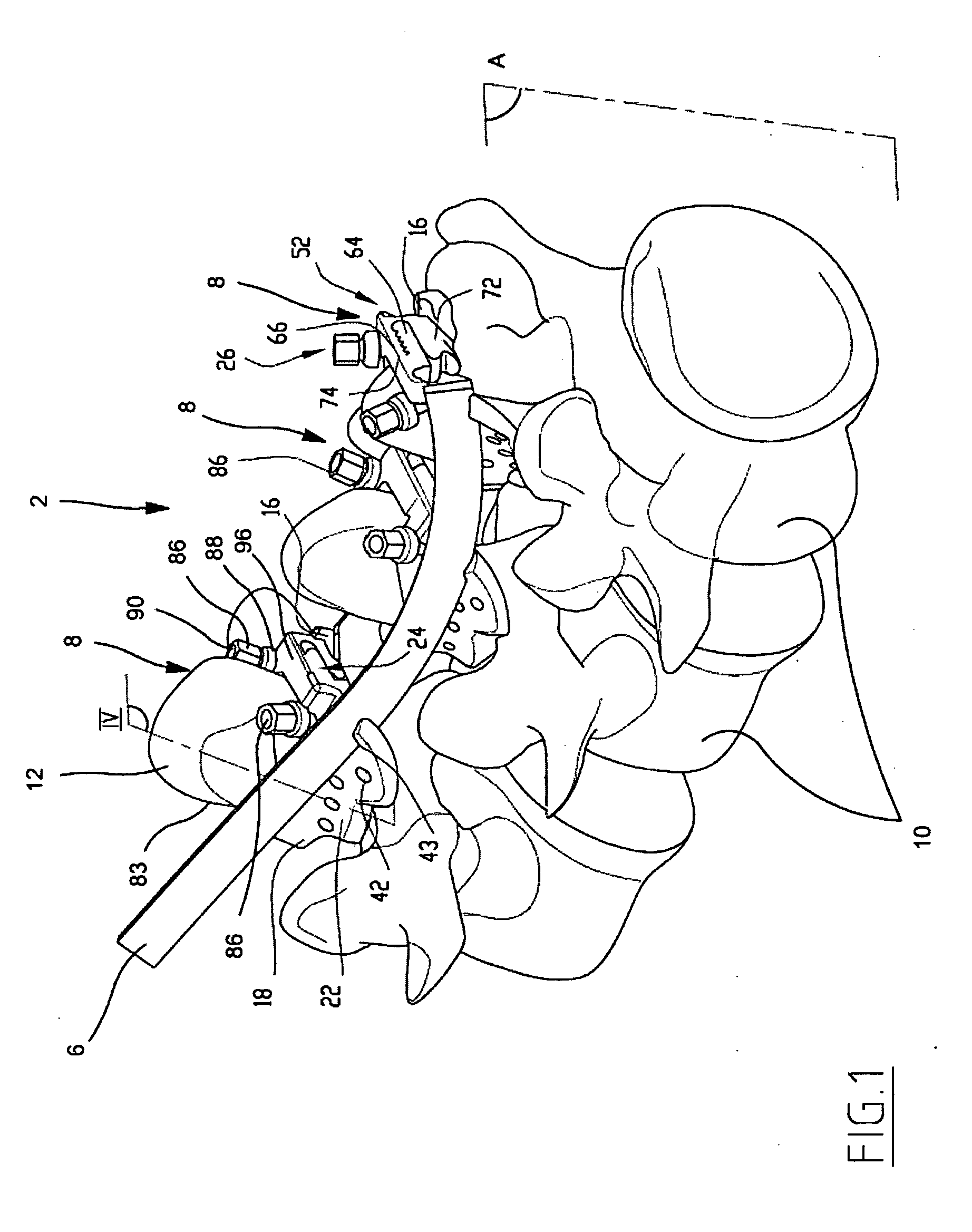
[0030]FIG. 1 illustrates a vertebral osteosynthesis device 2 for the posterior route comprising two longitudinal elements, a left longitudinal element 4 and a right longitudinal element 6 (for greater clarity only the right one is represented in FIG. 1; the two longitudinal elements 4, 6 are visible in FIG. 3), and three linking elements 8 between the longitudinal elements 4, 6 and three successive vertebrae 10. In the example illustrated, the vertebrae are L3, L4, and L5. However, the device 2 could also be inserted on the thoracic vertebrae and / or other lumbar vertebrae.

[0031]In the entire description, the terms “inferior,”“superior,”“posterior,” and “anterior” are understood to be with respect to the vertebrae 10. They are understood to refer to the standing position of the patient. The terms “left” and “right” are understood to be with respect to the patient seen from the back, which corresponds to the view of the patient's body during the posterior approach.

[0032]The left longi...


PUM


Abstract

A linking element between a longitudinal element of a vertebral osteosynthesis device and a vertebra that comprises a left part and a right part, each intended to extend on a respective side of the spinous process of the vertebra. The left part and the right part each delimit a spinous surface and a laminary surface, and include a tightening means to bring them closer to each other, and tightens them on the spinous process by integrally connecting them to each other. The left part and the right part each delimit a reception recess for the longitudinal element and include immobilization means for the linking element assembled on the vertebra.An osteosynthesis device comprising at least one such linking element.

Description

BACKGROUND OF THE INVENTION[0001]The present invention concerns the field of prostheses called “vertebral osteosynthesis devices” and is intended to be implanted on the spinal column of a patient.[0002]Various pathologies may require the implantation of such a device, such as damage to the vertebrae and / or the disks that separate them, as a result of a degenerative disease, a tumor or a trauma, or a misalignment of the vertebrae with respect to their normal position. Their purpose is to integrally connect two or more consecutive vertebrae in a predetermined relative position. For this purpose, one often uses longitudinal elements, such as rods or elongated plates that extend along the spinal column and are fixed to the vertebrae by various means.[0003]These longitudinal elements can be fixed to the column using an anterior surgical approach or a posterior surgical approach. The two approaches have advantages and disadvantages, and the choice of method by the surgeon must be made as ...

Claims


Application Information

Patent Timeline
IPC IPC(8): A61B17/70
CPCA61B17/701A61B17/7068A61B17/7047
Inventor LIU, MINGYANJOSSE, LOIC
Owner WARSAW ORTHOPEDIC INC
Features
  • R&D
  • Intellectual Property
  • Life Sciences
  • Materials
  • Tech Scout
  • Unparalleled Data Quality
  • Higher Quality Content
  • 60% Fewer Hallucinations
Learn More